Wireless foot control system with optical transmitter and transceiver

a foot control and optical transmitter technology, applied in the field of foot operated control units, can solve the problems of limited control options, inconvenient use of hard-wired connection between the control unit and the controlled device, and difficulty in changing the control function without cable and/or connector modification

Inactive Publication Date: 2008-09-23
LINEMASTER SWITCH CORP
View PDF23 Cites 58 Cited by
  • Summary
  • Abstract
  • Description
  • Claims
  • Application Information

AI Technical Summary

Problems solved by technology

In many applications, the use of a hard-wired connection between the control unit and the controlled device can be inconvenient.
This limits the number of control options that can be controlled through the hard-wired connection.
In addition, it is generally difficult to change the control functions without cable and / or connector modification.
The conductors and / or insulation of exposed cables may be damaged if walked upon.
Heavily armored cord sets are unacceptably stiff and bulky for many applications.
Cable clutter is unaesthetic and makes “house cleaning” more difficult.
However, the RF signals used by the control units can interfere with the operation of other equipment that is located within the range of the control unit.
Conversely, other sources of RF energy may interfere with signal from the RF control unit.
Accordingly, RF control units are not appropriate for controlling certain types of controlled equipment, for example medical equipment.
LOS is also limited by off-LOS alignment of the transmitter and receiver.
However, an NLOS approach requires greater sophistication in the design of the transmitter and receiver.

Method used


Image

  • Wireless foot control system with optical transmitter and transceiver
  • Wireless foot control system with optical transmitter and transceiver
  • Wireless foot control system with optical transmitter and transceiver

Examples


Embodiment Construction

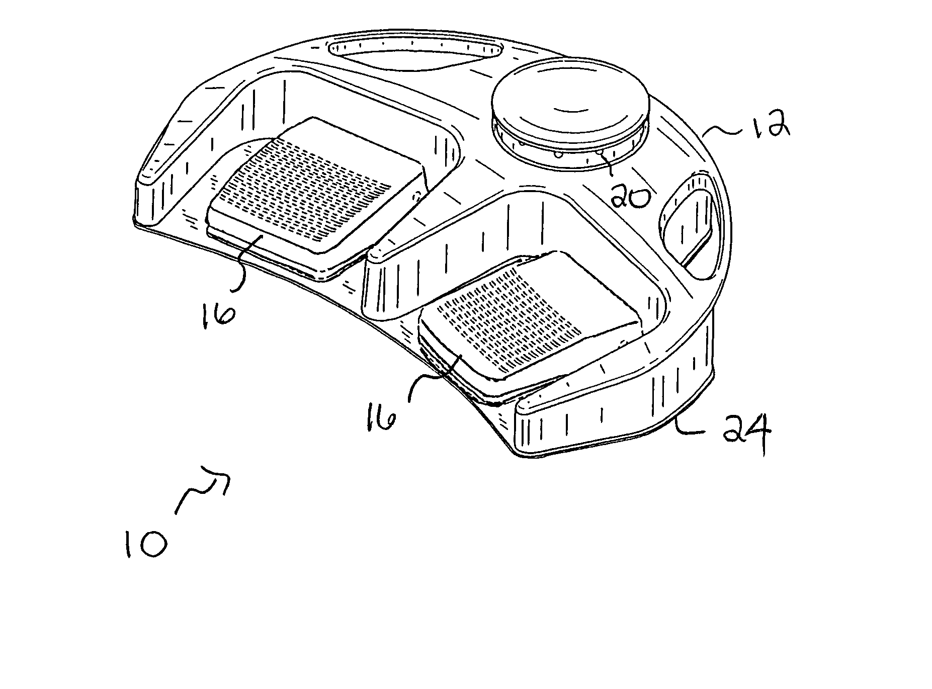
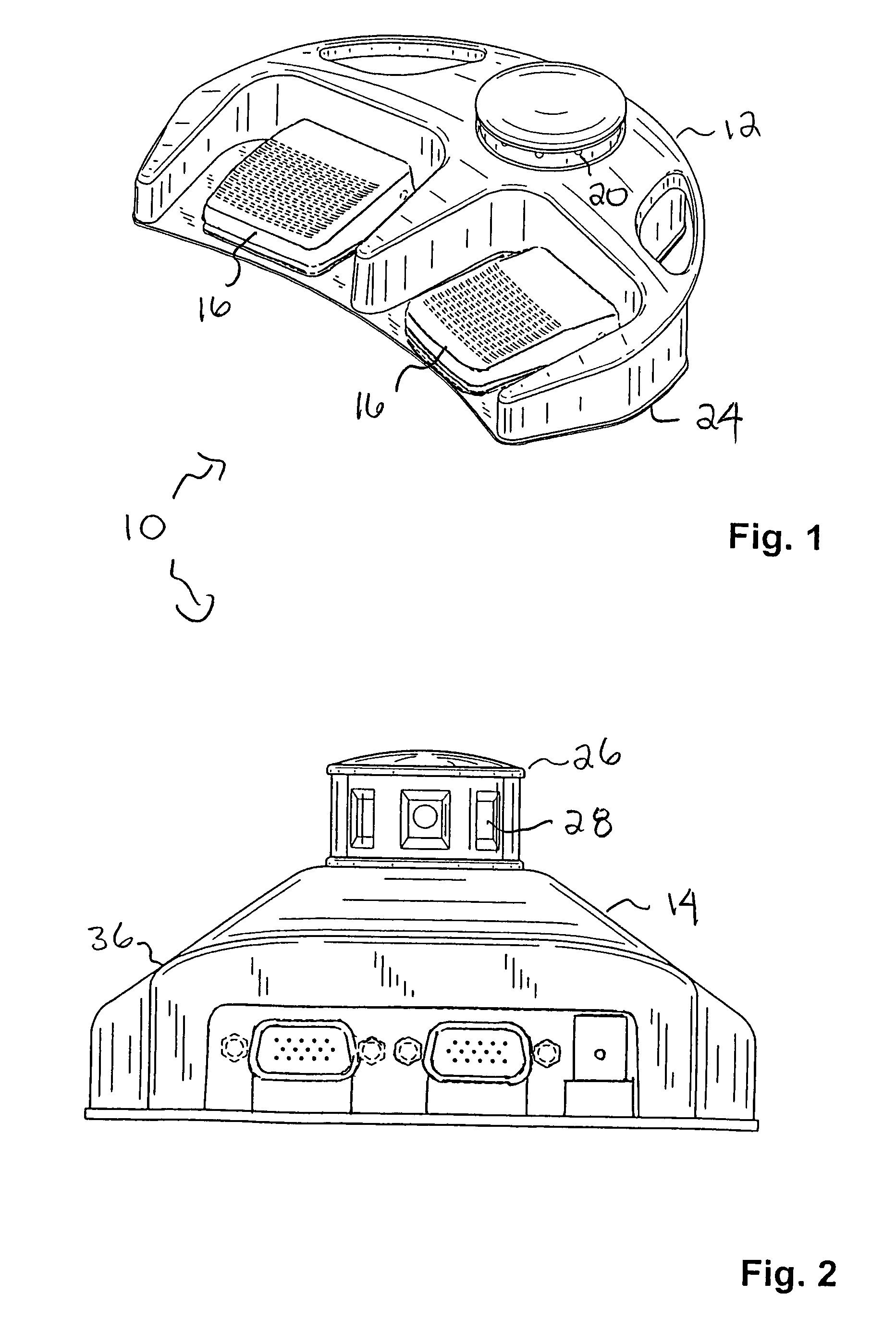
[0036]With reference to the drawings wherein like numerals represent like parts throughout the several figures, a wireless foot control system 10 in accordance with the present invention comprises two major subsystems, a transmitter 12 (FIG. 1) that communicates with a receiver 14 (FIG. 2), using a given medium.

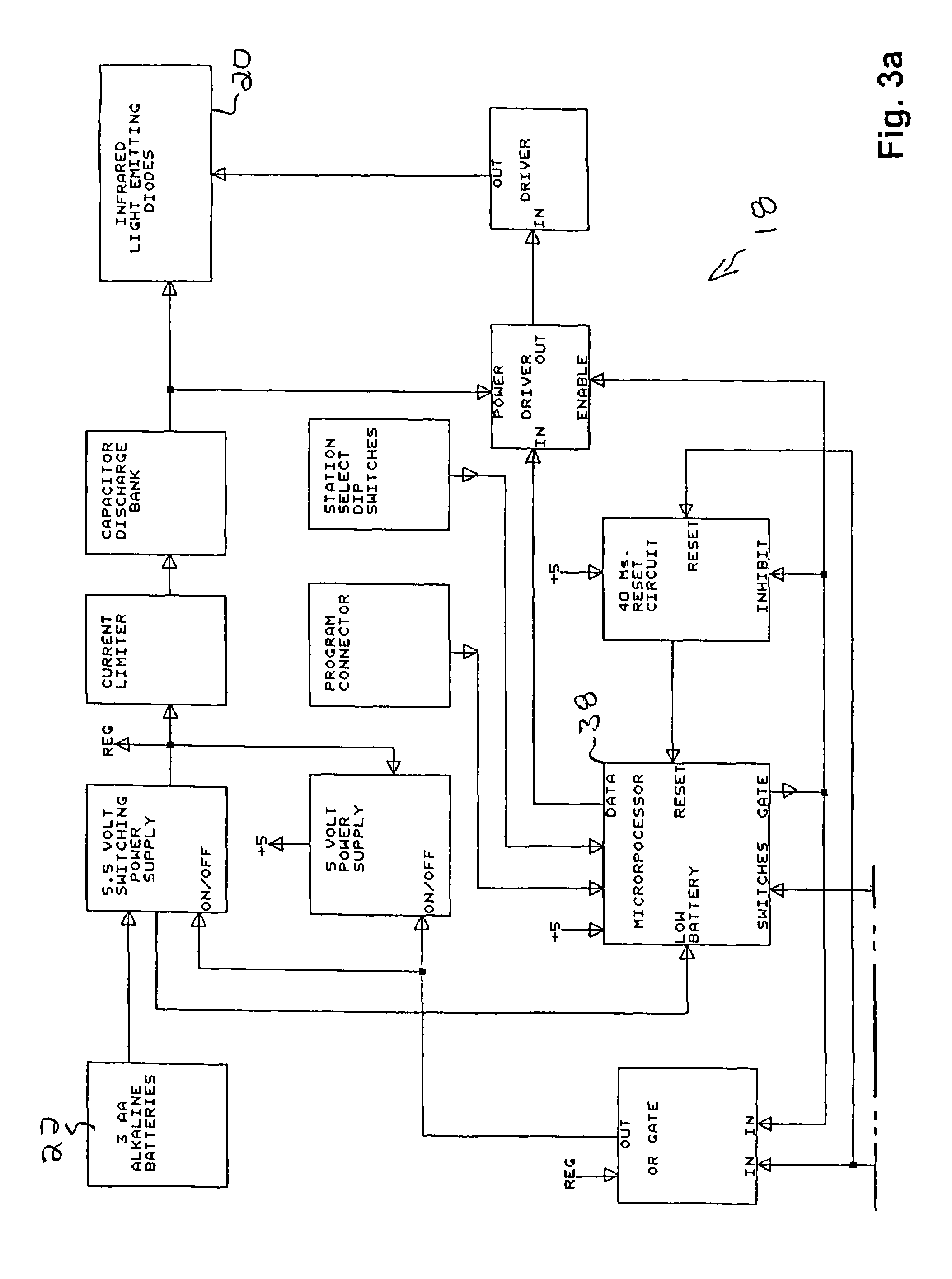
[0037]With additional reference to FIGS. 3a and 3b, the transmitter 12 includes at least one foot pedal 16 that functions as a switch mechanism for initiating an electrical control signal. Electronic circuitry 18 is activated by closing the switch mechanism to produce the control signal in a format which can be transmitted and received over the communication medium. A medium generator 20 produces the communication medium. A power source 22 of a pre-selected design, such as a battery, supplies power to the medium generator 20 through a power supply 21 of the electronic circuitry 18. The power supply 21 comprises a capacitor bank 23 which is charged through a current limiter 25...


PUM


Abstract

A wireless foot control system includes a receiver and at least one transmitter. The transmitter includes a medium generator for emitting a communication medium, a power supply and at least one foot pedal. The power supply includes a power source, a capacitor bank having a discharge current capacity sufficient to power the medium generator, and a current limiter. The current limiter connects the power source to the capacitor bank, charging the capacitor bank from the power source over a period of time. The foot pedal selectively energizes the medium generator from the capacitor bank. The receiver includes a medium collector for collecting the emitted medium and an electronic circuit. The electronic circuit includes a converter for converting the collected medium to an input control signal and a microprocessor in communication with the converter, the microprocessor having an operating system for generating an output control signal commensurate with the input control signal.

Description

BACKGROUND OF THE INVENTION[0001]This invention relates generally to control units for controlling the operation of associated power driven devices such as medical and dental equipment, power tools, recording equipment, office machines, and motor driven appliances. More particularly, the present invention relates to foot operated control units wherein the control unit is actuated by the foot of the operator to energize, de-energize, or similarly control the operation of an associated power driven device.[0002]Most conventional foot operated control units are connected to the controlled device by a cord or cable that carries the command signal from the control unit to the controlled device or completes the power supply circuit between the control unit and the controlled device. In many applications, the use of a hard-wired connection between the control unit and the controlled device can be inconvenient. For example, the cable and its connectors have a limited number of conductors an...

Claims


Application Information

Patent Timeline
Patent Type & Authority Patents(United States)
IPC IPC(8): G05B11/01G05B15/00H01H3/22H02P1/00H02P1/04H02P25/18H02P3/00H02P5/00H02P7/00
CPCG06F3/0383G06F3/0334
Inventor REYNOLDS, CHARLES A.ARGRAVES, GARY L.
Owner LINEMASTER SWITCH CORP
Why Eureka
Try Eureka