Automatic dispersion compensation in amplification for short pulse fiber laser system

a fiber laser and automatic technology, applied in the direction of laser details, basic electric elements, electrical equipment, etc., can solve the problems of limited cpa systems, limited cpa systems, and limited cpa technology, and achieve the effect of significant increase in laser power

Active Publication Date: 2008-09-30
POLARONYX
View PDF6 Cites 11 Cited by
  • Summary
  • Abstract
  • Description
  • Claims
  • Application Information

AI Technical Summary

Benefits of technology

[0006]Specifically, it is an aspect of the present invention that a short pulse fiber laser amplification system is implemented with a gain fiber that carries out an amplification function and simultaneously compresses the laser pulses such that a separate compressor is no longer necessary when the compression takes place inside the amplification chain.
[0008]It is another aspect of this invention that an isolator is placed before the pulse width stretcher to block any reflection back to the seed laser thus the system is immune to perturbations and is able to generate significantly increased laser power.

Problems solved by technology

Even though current technologies of fiber laser have made significant progress toward achieving a compact and reliable fiber laser system providing high quality output laser with ever increasing output energy, however those of ordinary skill in the art are still confronted with technical limitations and difficulties.
Specifically, in a fiber laser system implemented with the Chirped Pulse Amplification (CPA) for short pulse high power laser amplifier, the CPA systems are still limited by the technical difficulties that the third order dispersion (TOD) limits the scalability of the laser systems.
Such limitations were not addressed in the conventional technologies due to the fact that the conventional solid-state laser utilizes Grating-Lens combination and Treacy compressor for pulse stretching and compressing.
Ideally, in such solid-state systems, all orders of dispersion can be compensated, but the material dispersion can distort and damage this ideal situation.
However, for a fiber laser system, the situation is different due to the fact that in the fiber laser systems, attempts are made by using the fiber stretcher to replace the grating-lens combination for the purpose of significantly increasing the system reliability.
However, the TOD limits the ability for de-chirping when using Treacy compressor since both fiber stretcher and Treacy compressor have positive TOD even this combination can remove the second order dispersion completely.
This issue of TOD dispersion makes it more difficult to develop a high-energy fiber laser amplifier with <200 fs pulse width.
Actually, the technical difficulty of TOD dispersion is even more pronounced for laser system of higher energy.
Therefore, for laser system of higher energy, it is even more difficult to re-compress the pulse to the original pulse width.
However, such systems still encounter technical difficulties in recompress the pulse width.
Furthermore, the commercially available PBG fibers are too lossy, e.g., 0.1˜0.2 dB / m.
The splicing loss between the PBG fiber and the single mode fiber is 1 to 2 dB that may lead to a total loss as large as 10 dB when the PGB fiber is placed after the amplification chain.

Method used


Image

  • Automatic dispersion compensation in amplification for short pulse fiber laser system
  • Automatic dispersion compensation in amplification for short pulse fiber laser system
  • Automatic dispersion compensation in amplification for short pulse fiber laser system

Examples


Embodiment Construction

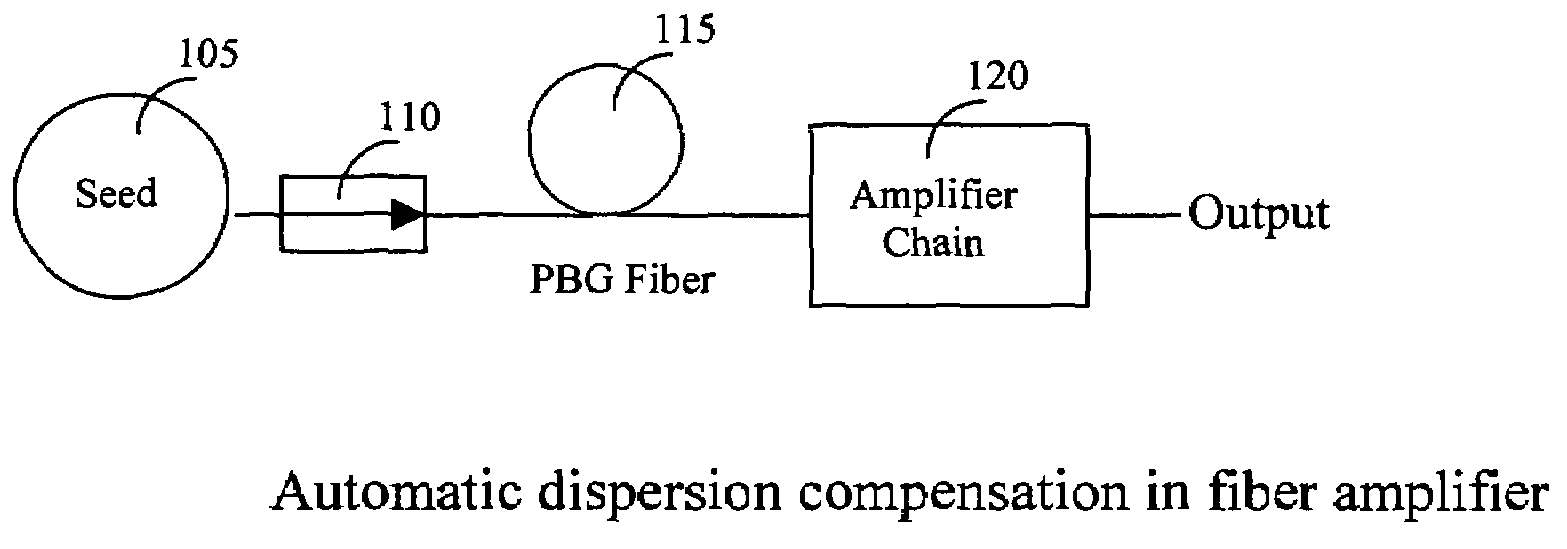
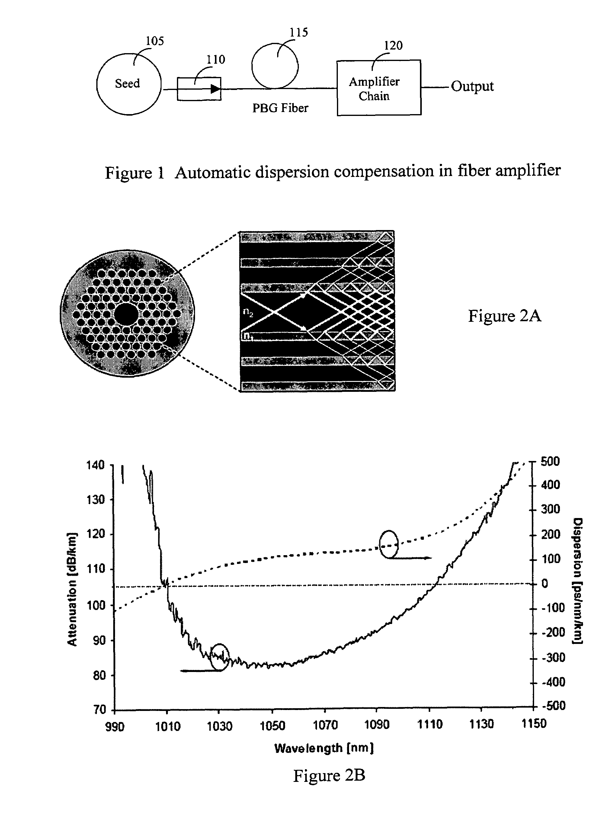
[0019]Referring to FIG. 1 for a schematic diagram of a fiber laser system 100 of this invention that implements a dispersion compensator of this invention. The laser system 100 includes a laser seed 105 for generating a seed laser for projecting into an isolator 110 then to a laser stretcher 115 implemented as PBG fiber to stretch the laser pulse. The stretcher 115 generates laser pulse with stretched pulse width is projected into a series of laser amplifiers 120 to amplify the laser into higher energy. These series of amplifiers 120 simultaneously carry out a pulse width compression function by compressing the laser pulses.

[0020]The stretcher 115 is implemented with a PBG fiber and unlike the common silica core fiber, the Photonic Bandgap (PBG) fiber guides the light in a hollow core, surrounded by a micro-structured cladding formed by a periodic arrangement of air holes in silica. The special structure of the PBG fiber presents two immediate advantages. First of all, since only a ...


PUM


Abstract

A fiber Chirped Pulse Amplification (CPA) laser system includes a fiber mode-locking oscillator for generating a laser for projecting to a fiber stretcher for stretching a pulse width of the laser wherein the stretcher further comprising a Photonic Bandgap (PBG) fiber having a lower nonlinearity and an abnormal dispersion than a solid core fiber for connecting and transmitting a laser from the stretcher to a multistage amplifier for amplifying the laser into an output laser whereby a separate compressor is not required.

Description

[0001]This Formal Application claims a Priority Date of Aug. 29, 2005 benefited from a Provisional Patent Applications 60 / 713,650, 60 / 713,653, and 60 / 713,654 and a Priority Date of Sep. 1, 2005 benefited from Provisional Applications 60 / 714,468 and 60 / 714,570 filed Sep. 7, 2005 by one of the same Applicants of this Application.FIELD OF THE INVENTION[0002]The present invention relates generally to apparatuses and methods for providing fiber laser system. More particularly, this invention relates a design for automatic dispersion compensation in the amplification chain implemented in a Chirped Pulse Amplification (CPA) fiber laser system.BACKGROUND OF THE INVENTION[0003]Even though current technologies of fiber laser have made significant progress toward achieving a compact and reliable fiber laser system providing high quality output laser with ever increasing output energy, however those of ordinary skill in the art are still confronted with technical limitations and difficulties. S...

Claims


Application Information

Patent Timeline
Patent Type & Authority Patents(United States)
IPC IPC(8): H01S3/30
CPCH01S3/0064H01S3/06758H01S3/06741H01S3/06725Y10S372/70
Inventor LIU, JIANXIA, JIANGFAN
Owner POLARONYX
Why Eureka
Try Eureka