Labyrinth seal in a stationary gas turbine

a technology of stationary gas turbine and labyrinth seal, which is applied in the direction of liquid fuel engines, machines/engines, manufacturing tools, etc., can solve the problems leakage flows, and achieve the effect of reducing the efficiency of stationary gas turbines

Inactive Publication Date: 2008-10-07
SIEMENS AG
View PDF12 Cites 30 Cited by
  • Summary
  • Abstract
  • Description
  • Claims
  • Application Information

AI Technical Summary

Benefits of technology

[0012]By carrying out the working steps of the invention, it is now possible for the first time for the arrangement of stacked labyrinth seals which is known from aircraft turbines also to be transferred to stationary gas turbines. It is therefore possible for a plurality of labyrinth seals which are stacked radially on top of one another to be arranged in a stationary gas turbine with a parting plane, and for the improved sealing action which ensues to be utilized for a stationary gas turbine. The leakage flow which reduces the efficiency of the stationary gas turbine is considerably reduced as a result.
[0013]The space required for the radially stacked labyrinth seals is reduced compared to the terraced arrangement. In particular, the size of the seal and of the entire inner ring in the axial direction have been reduced.
[0020]It is advantageous for the sealing surfaces and the sealing teeth provided on the balconies to be designed in such a manner that intended axial displacement of the rotor counter to the direction of flow of the working fluid is possible without any change in the sealing action. Consequently, while the gas turbine is operating the rotor can be displaced without any deterioration in the sealing action. This is important in particular if the gap between the rotor blade tip and the radially outer, conical inner wall of the hot gas duct is to be reduced in size by the displacement of the rotor.

Problems solved by technology

The leakage flow which reduces the efficiency of the stationary gas turbine is considerably reduced as a result.

Method used


Image

  • Labyrinth seal in a stationary gas turbine
  • Labyrinth seal in a stationary gas turbine
  • Labyrinth seal in a stationary gas turbine

Examples


Embodiment Construction

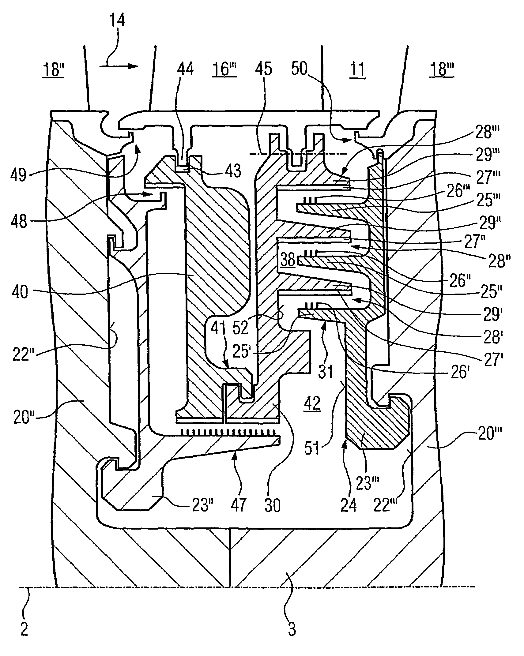
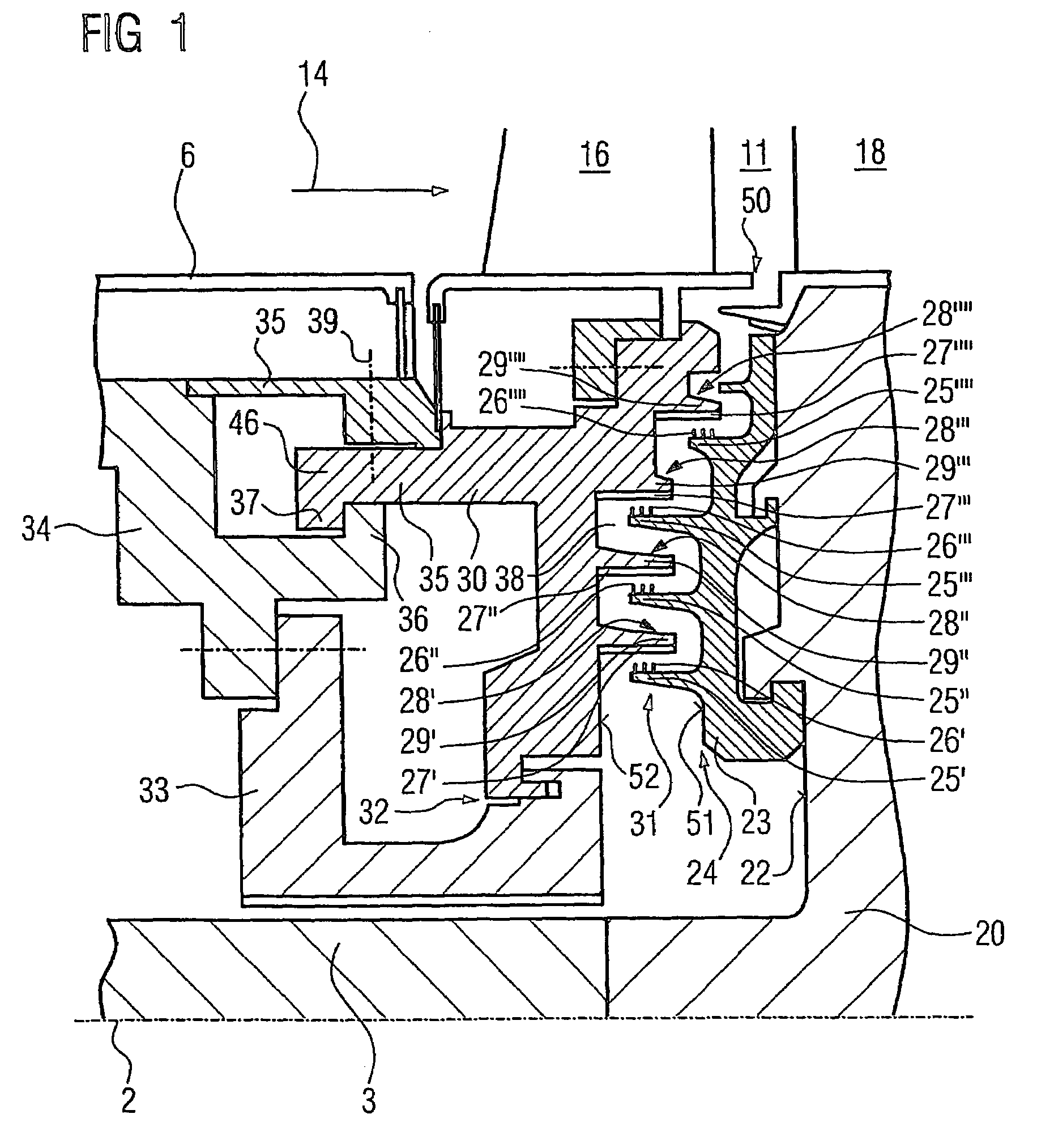
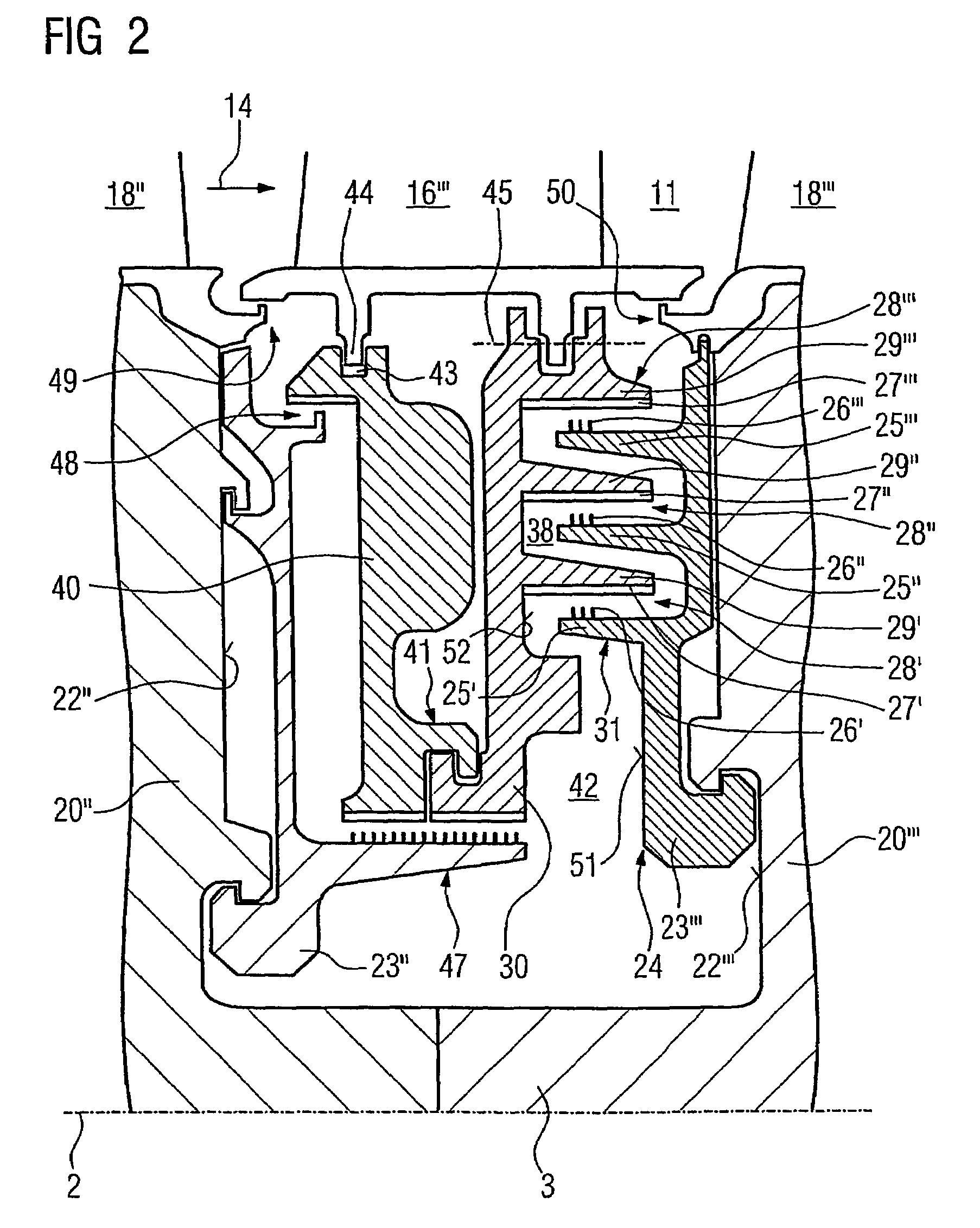
[0025]FIG. 3 shows a stationary gas turbine 1 in the form of a partial longitudinal, section. In its interior, it has a rotor 3, which is mounted such that it can rotate about an axis of rotation 2 and is also referred to as the turbine rotor or rotor shaft. An intake housing 4, a compressor 5, a toroidal annular combustion chamber 6 with a plurality of coaxially arranged burners 7, a turbine 8 and the exhaust-gas housing 9 follow one another along the rotor 3. The annular combustion chamber 6 in this case forms a combustion space 10 which is in communication with an annular hot-gas duct 11, where four turbine stages 12 connected in series form the turbine 8. Each turbine stage 12 is formed from two blade / vane rings. As seen in the direction of flow of a working fluid 14, a guide vane ring 17 is followed in the hot-gas duct 11 by a ring 15 formed from rotor blades 18. The guide vanes 16 are secured to the stator 19, whereas the rotor blades 18 of a ring 15 are secured to the rotor 3...


PUM

PropertyMeasurementUnit
inner diameteraaaaaaaaaa
arc lengthaaaaaaaaaa
stabilityaaaaaaaaaa

Abstract

The invention relates to a segmented inner ring for holding guide blades. According to the invention, a lateral wall opposing the front side of the inner ring and pertaining to a shaft shoulder formed on the rotor shaft extends radially, and respectively one half of a labyrinth seal is formed on the front side of the inner ring and on the shaft shoulder. The aim of the invention is to apply an arrangement of stacked labyrinth seals, known from airplane turbines, to a stationary gas turbine having a separation plane. To this end, a method is used to mount an inner ring of a gas turbine. The invention also relates to a stationary gas turbine comprising a segmented inner ring.

Description

CROSS REFERENCE TO RELATED APPLICATIONS[0001]This application is the US National Stage of International Application No. PCT / EP2004 / 008052, filed Jul. 19, 2004 and claims the benefit thereof. The International Application claims the benefits of European Patent application No. 03019002.9 EP filed Aug. 21, 2003. All of the applications are incorporated by reference herein in their entirety.FIELD OF THE INVENTION[0002]The invention relates to a stationary gas turbine having a segmented inner ring for holding guide vanes. It also relates to a method for assembling a segmented inner ring for guide vanes of a stationary gas turbine.BACKGROUND OF THE INVENTION[0003]DE 37 12 628 has disclosed an inner ring for holding guide vanes of a stationary gas turbine. The guide vanes which are arranged in a star shape around the rotor to form a guide vane ring are secured to the housing of the gas turbine by means of their radially outer guide vane roots. The radially extending guide vanes, on their s...

Claims


Application Information

Patent Timeline
Patent Type & Authority Patents(United States)
IPC IPC(8): F01D11/02F01D5/30F01D11/00F16J15/447
CPCF01D5/3015F01D11/001F01D11/02F16J15/4476F01D11/006Y10T29/49323
Inventor TIEMANN, PETER
Owner SIEMENS AG
Why Eureka
Try Eureka