NMR spectrometer with a common refrigerator for cooling an NMR probe head and cryostat

a technology of nmr probe head and refrigerator, which is applied in the direction of superconducting magnets/coils, optical radiation measurement, magnetic materials, etc., can solve the problems of thermal radiation loss caused by thermal conduction and thermal radiation, less compact structure of this design, and not being used in modern magnet cryostats, etc., to achieve the effect of improving the effectivity of the overall system, increasing the efficiency of the overall apparatus, and increasing the power

Active Publication Date: 2008-10-07
BRUKER BIOSPIN
View PDF11 Cites 15 Cited by
  • Summary
  • Abstract
  • Description
  • Claims
  • Application Information

AI Technical Summary

Benefits of technology

[0012]The overall cooling power is generated outside of the cryostat by a refrigerator and is transferred using suitable coolants via an insulated transfer line to the components to be cooled. This prevents mechanical and magnetic disturbances of the magnetic field by the refrigerator and also permits utilization of the excess energy produced in the different cooling circuits for cooling further cooling circuits. Moreover, the more variable arrangement of the heat exchangers permits more effective setting of the pre-cooling temperature to save energy.
[0024]In a special embodiment of the inventive NMR spectrometer, the cryostat contains a helium tank and a Joule-Thomson valve which is disposed in the helium tank and is integrated in one of the cooling circuits. In this Joule-Thomson valve, the helium flow is further cooled due to adiabatic relaxation to cool the helium tank, and is partially liquefied. The temperature after relaxation is lower than the temperature of the second stage of the refrigerator, e.g. 6 Kelvin at the refrigerator and 4.2 K downstream of the Joule-Thomson valve. The second refrigerator stage can accept a considerably larger amount of power in consequence of this temperature increase, compared to cooling of the coolant to 4.2 K without a Joule-Thomson valve (100-300%). The NMR probe head usually requires more power in the lower temperature range than the helium tank of the cryostat. Moreover, it is not necessary to cool the NMR probe head to 4.2 K. The Joule-Thomson valve can split the power of the second stage into two temperature levels. The effectivity of the overall system is thereby considerably improved. In a particularly advantageous manner, the housing containing the cold head and the heat exchangers is disposed above the cryostat. In this arrangement, the pump for circulating the coolant and the associated valves can be omitted due to gravity and inherent convection of the coolant. No additional heat is input through pump operation and the efficiency of the overall apparatus is increased.

Problems solved by technology

The thermal loss caused by thermal conduction and thermal radiation is therefore a problem.
The structure of this design is less compact and it is therefore not used in modern magnet cryostats.
In this case, part of the cooling power is also “wasted”, without being used.
The installation of the refrigerator in the magnet cryostat, however, entails considerable disadvantages.
The generally magnetic regenerator material is located within the stray field of the NMR magnet coil and therefore generates magnetic disturbances.
The vibrations which are caused directly by the refrigerator deteriorate the measuring conditions.
Moreover, the limited space within the magnet cryostat prohibits arbitrary positioning of the heat exchangers, which limits the possibility of setting the pre-cooling temperature.
For this reason, these devices frequently fail to reach an optimum cooling operation.
A considerable part of the input power of the cooler, which is approximately 4 to 8 kW, is still lost in these conventional devices.

Method used


Image

  • NMR spectrometer with a common refrigerator for cooling an NMR probe head and cryostat
  • NMR spectrometer with a common refrigerator for cooling an NMR probe head and cryostat
  • NMR spectrometer with a common refrigerator for cooling an NMR probe head and cryostat

Examples


Embodiment Construction

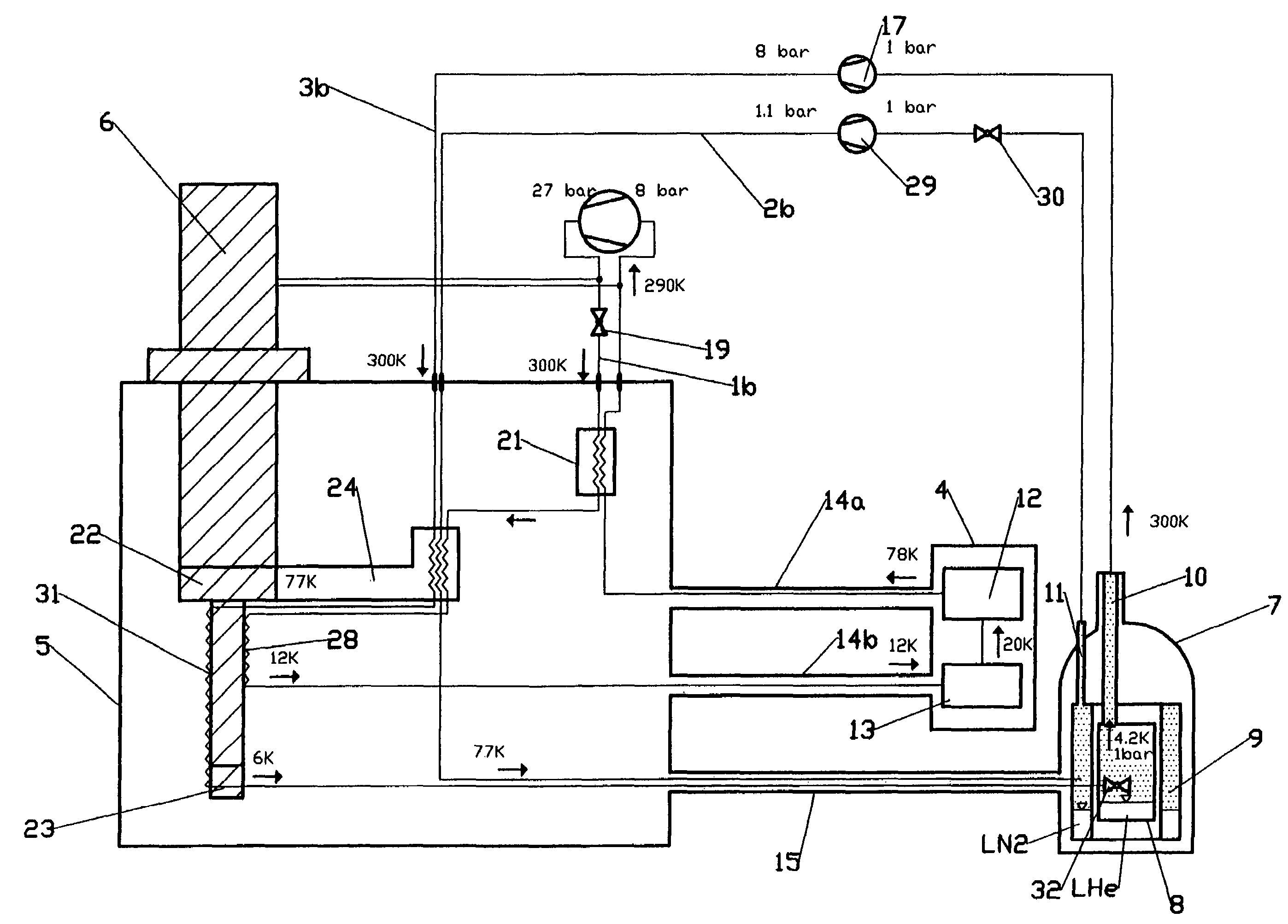
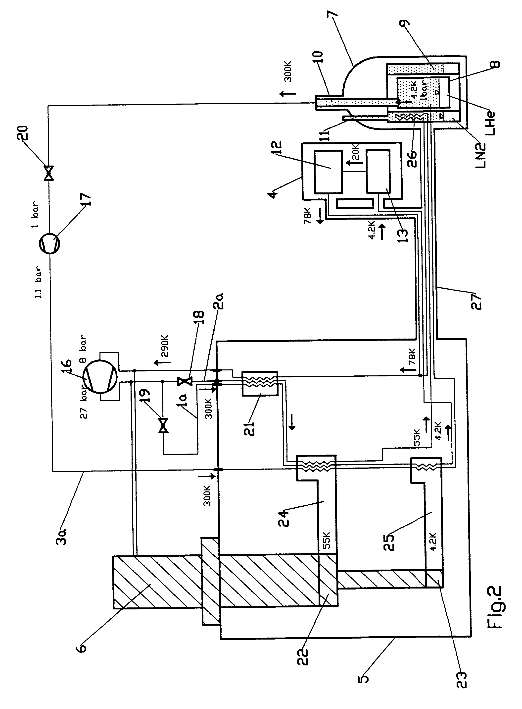
[0031]The figures explained below show different embodiments of the inventive NMR spectrometer with associated cooling circuits 1a, 1b, 1c, 1d, 2a, 2b, 3a, 3b. The NMR spectrometer also comprises a cryostat, an NMR probe head 4 and a cold head 6 of a refrigerator which is preferably designed as a pulse tube cooler and disposed in a separate evacuated and thermally insulated housing 5 to prevent thermal input through convection and gas heat conduction. The drawings do not show the insulation from thermal radiation.

[0032]The essential components of the cryostat are an outer shell 7 and a helium tank 8 which contains a superconducting magnet and liquid helium (4.2 K), a nitrogen tank 9 which contains liquid nitrogen and one or more neck tubes 10 which connect the helium tank 8 to the outer shell 7. The nitrogen tank 9 also comprises one or more neck tubes 11 of this type.

[0033]The NMR probe head 4 contains the resonator 13 and the pre-amplifier 12. Each coolant is transported through v...


PUM

PropertyMeasurementUnit
temperatureaaaaaaaaaa
temperaturesaaaaaaaaaa

Abstract

An NMR spectrometer comprising a magnet coil system disposed in the helium tank (8) of a cryostat and an NMR probe head (4) which is disposed in a room temperature bore of the cryostat and contains a cooled RF resonator (13) for receiving NMR signals from a sample to be examined, wherein the helium tank (8) and the NMR probe head (4) are cooled by a common, multi-stage, compressor-operated refrigerator, is characterized in that the common refrigerator comprises a cold head (6) and several heat exchangers (21, 24, 25, 28, 31, 33, 34) at different temperature levels, wherein the refrigerator is disposed at a spatial separation from the cryostat in a separate, evacuated and thermally insulated housing (5), and several cooling circuits (1a, 1b, 1c, 1d, 2a, 2b, 3a, 3b) having thermally insulated transfer lines (14a, 14b, 15) are provided between the housing (5) containing the heat exchangers (21, 24, 25, 28, 31, 33, 34) and the cryostat, and also between the housing (5) and the NMR probe head (4). The probe head and magnet cryostat of the inventive NMR spectrometer can thereby be cooled by a common refrigerator, wherein the cooling resources of the used refrigerator are optimally utilized.

Description

[0001]This application claims Paris Convention priority of DE 10 2004 053 972.3 filed Nov. 09, 2004 the complete disclosure of which is hereby incorporated by reference.BACKGROUND OF THE INVENTION[0002]The invention concerns an NMR spectrometer comprising a magnet coil system which is disposed in the helium tank of a cryostat, and an NMR probe head which is disposed in a room temperature bore of the cryostat and contains a cooled RF resonator for receiving NMR signals from a sample to be examined, wherein the helium tank and the NMR probe head are cooled by a common, multi-stage, compressor-operated refrigerator.[0003]A device of this type is disclosed in WO 03 / 023433 A1.[0004]The NMR probe head of an NMR spectrometer is located, together with a measuring device, in the bore of a magnet cryostat. This magnet cryostat contains a superconducting coil which generates the magnetic field required for NMR measurements. The NMR probe head as well as the magnet cryostat must be kept at very...

Claims


Application Information

Patent Timeline
Patent Type & Authority Patents(United States)
IPC IPC(8): F25B19/00B01D59/44H01F6/04H01J49/40F25B9/02F25B9/10F25B9/14F25B25/00G01R33/31
CPCF25B9/02G01R33/31F25B9/10F25B9/14F25B9/145F25B2309/1407F25B2309/1413F25D19/006H01F6/04G01R33/46
Inventor STROBEL, MARCO
Owner BRUKER BIOSPIN
Why Eureka
Try Eureka