
Compact noise silencer for an air blower

a noise silencer and air blower technology, applied in the field of noise silencers for air blowers, can solve the problems of difficult, if not impossible, installation of sound silencers, and relatively large size of commercially available sound silencers, and achieve the effects of reducing overall length, reducing costs, and being convenient to us

Active Publication Date: 2008-10-07
DURR SYST INC
View PDF47 Cites 26 Cited by
  • Summary
  • Abstract
  • Description
  • Claims
  • Application Information

AI Technical Summary

Benefits of technology

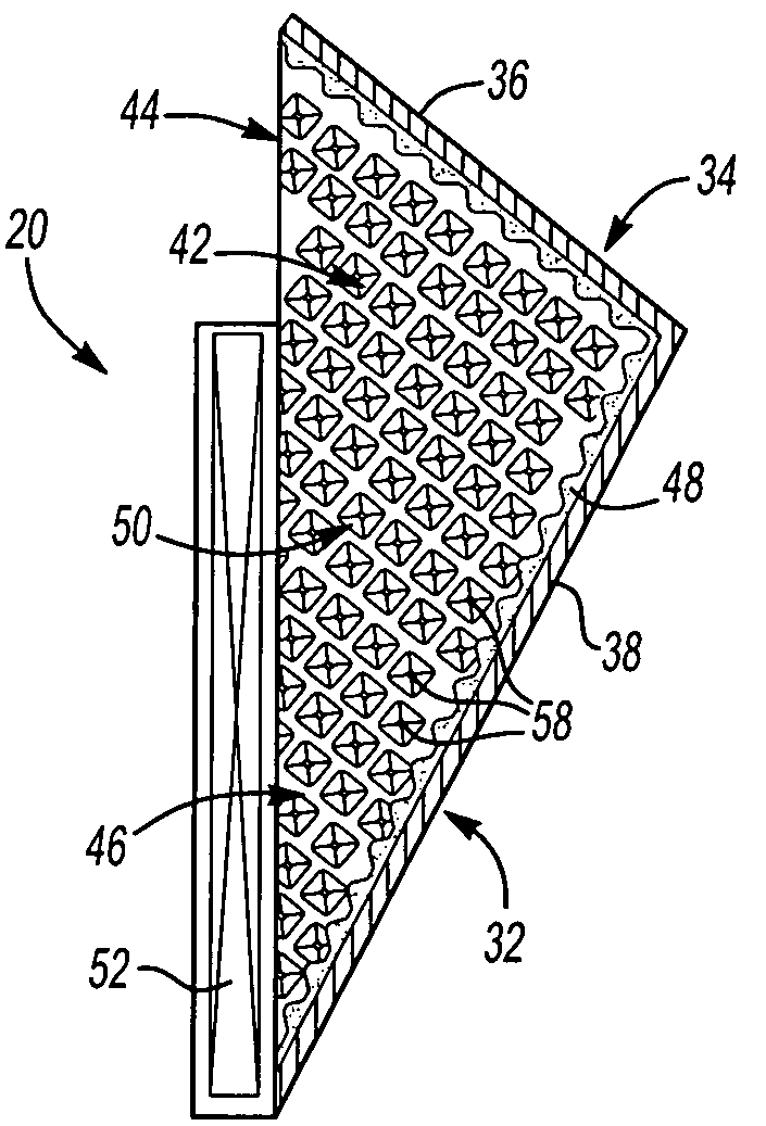
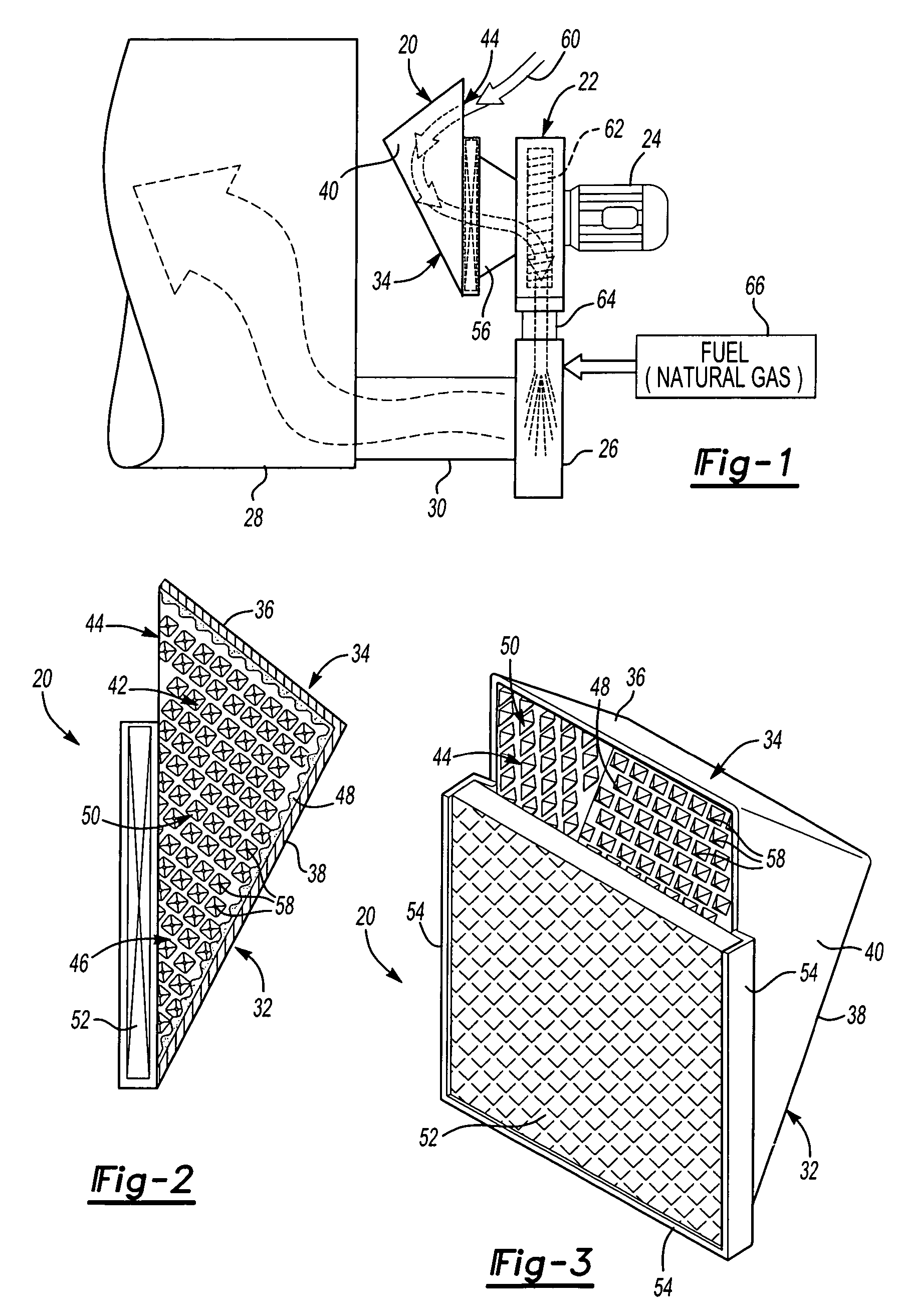
[0006]The noise silencer for an air blower of this invention includes a housing having an L-shaped back wall having a sound adsorbent material thereon, including a first back wall and a second back wall, opposed side walls defining a generally triangular enclosure, an air inlet opposite the first back wall and an air outlet opposite the second back wall communicating with a blower. In the embodiment of the noise silencer of this invention for a combustion burner, the air outlet of the housing communicates with a blower directing air under pressure into a burner. The compact noise silencer of this invention has a substantially reduced overall length compared to conventional commercially available noise silencers and is simpler in construction and therefore reduced costs. Air enters the air silencer of this invention through the air inlet, which may be located at the top of the housing opposite the first back wall, and the angles of the noise silencer assist in guiding the air through the housing with minimal measurable pressure drop. Further, the noise silencer of this invention results in sound attenuation equal to or greater than commercially available sound silencers for this application with reduced cost.

Problems solved by technology

However, one problem with commercially available sound silencers is their relatively large size.
Typically, space is limited around the inlet of the combustion air blower, making installation of the sound silencer difficult, if not impossible.
Further, commercially available sound silencers are relatively complex and therefore relatively expensive.
As set forth above, however, space is limited around the inlet of the combustion air blower in a typical application.

Method used


Image

  • Compact noise silencer for an air blower
  • Compact noise silencer for an air blower

Examples


Embodiment Construction

[0014]As set forth above, the air inlet and noise silencer of this invention may be utilized to supply heated air to a heater box such, as used by the automotive industry to supply heated air to a dryer or paint oven. However, the noise silencer of this invention may be utilized for any application requiring noise reduction or attenuation of a blower supplying air under pressure for subsequent application. The noise silencer of this invention is compact, efficient and simple in design, therefore having a reduced cost. As shown in FIG. 1, the disclosed embodiment of the air inlet and noise silencer 20 of this invention is connected to a conventional blower 22 having a motor 24. The blower 22 directs gas under pressure to a burner 26 which directs heated air to a heater box 28 through duct 30. As described above, however, the noise silencer of this invention may be utilized for other applications.

[0015]As best shown in FIGS. 2 and 3, the disclosed embodiment of the noise silencer 20 o...


PUM


Abstract

A compact noise silencer for a blower, including an L-shaped back wall having a sound adsorbent media and side walls defining a triangular enclosure, an inlet opposite one portion of the back wall and a central outlet opposite the back wall having a filter directing air into a blower. In the disclosed application, the blower directs air into a burner which heats the air for various applications.

Description

RELATED APPLICATIONS[0001]This application claims priority to provisional application Ser. No. 60 / 611,886 filed Sep. 21, 2004.FIELD OF THE INVENTION[0002]This invention relates to a noise silencer for an air blower, such as an air blower for a combustion burner. The noise silencer of this invention is far more compact than commercially available sound or noise silencers, but provide at least as good sound attenuation as conventional noise silencers at less cost.BACKGROUND OF THE INVENTION[0003]Heater boxes are typically used to supply heated air to an oven to bake a product, such as paint on a vehicle body or other coated substrates. In a typical application, air is directed under pressure by a fan or blower to a burner and the heated air is then directed from the burner to a heater box. The burner mixes fuel, typically natural gas, with air and uses an ignition source to cause combustion and generate heat. Heated air is then generally directed from the burner to a heater box which ...

Claims


Application Information

Patent Timeline
Patent Type & Authority Patents(United States)
IPC IPC(8): F02M35/00
CPCF23M20/005F04D29/664
Inventor DE BORCHGRAVE, ADRIENSPRINKLES, CLIFTON
Owner DURR SYST INC
Learn More