Vibration stress relief of weldments

a technology of vibration stress and weldments, which is applied in the direction of mechanical vibration separation, non-electric welding apparatus, machines/engines, etc., can solve the problems of difficult repair of diaphragms, high cost of replacement, and limited application prospects

Active Publication Date: 2008-10-07
SIEMENS ENERGY INC
View PDF2 Cites 2 Cited by
  • Summary
  • Abstract
  • Description
  • Claims
  • Application Information

AI Technical Summary

Benefits of technology

[0009]The use of vibration stress reduction during welding has been found to reduce the distortion of welded components during the welding process, in part due to the stress reduction.
[0010]Accordingly, it is an object of the present invention to provide a method of determining an ideal frequency for relieving stress within stainless steel combustion turbine diaphragms during welding.

Problems solved by technology

Such diaphragms may be exposed to temperatures from room temperature to about 900° F. These diaphragms are difficult to repair, and expensive to replace.
Presently available welding methods may produce significant distortion within the diaphragm, partly due to stresses created within the diaphragm from the welding process.
However, vibration stress relief has not previously been used for the 410 or 403 stainless steels typically used for diaphragms, in part because appropriate vibration frequencies have not been developed.
Stainless steel has a higher yield strength than other materials for which vibration stress relief has been used, increasing the difficulty of stress relief.
The diaphragm and other stainless steel components of combustion turbines are very prone to distortion, making stress relief during repair of these components critical.

Method used


Image

  • Vibration stress relief of weldments
  • Vibration stress relief of weldments
  • Vibration stress relief of weldments

Examples


Embodiment Construction

[0019]The present invention provides a method of stress relief for stainless steel components, for example, the diaphragm shroud of a combustion turbine, which is commonly made from 410 stainless steel or 403 stainless steel.

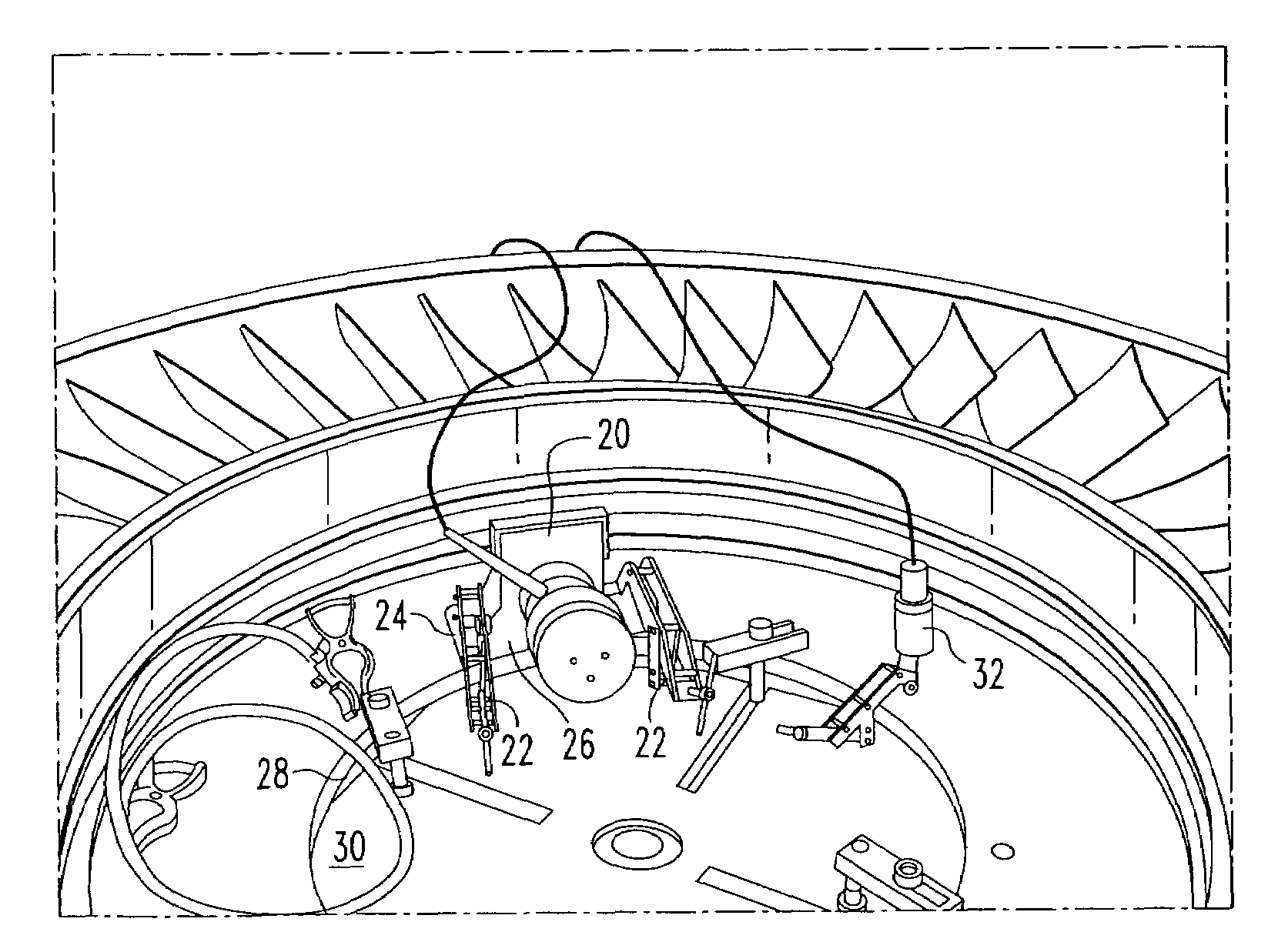
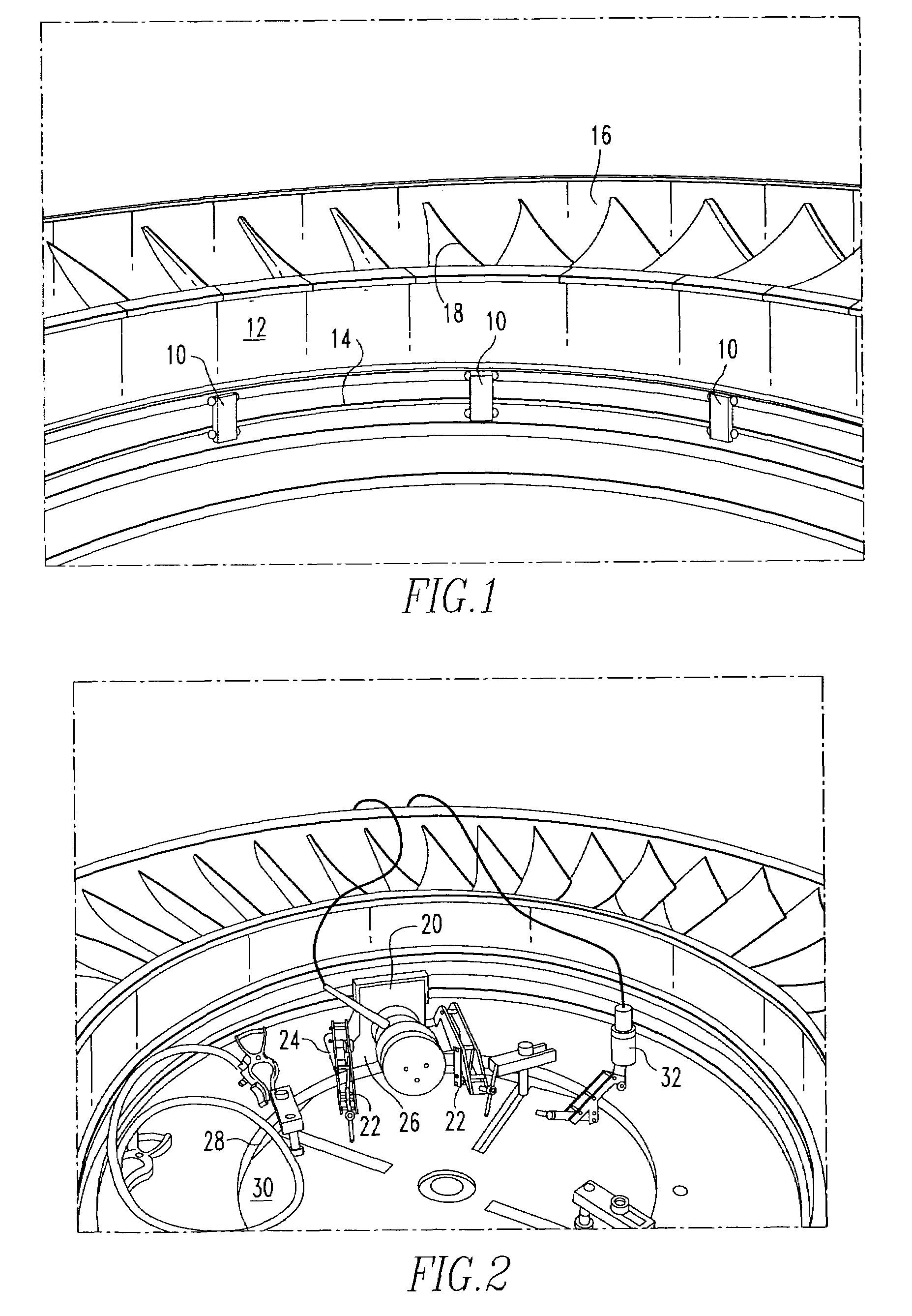
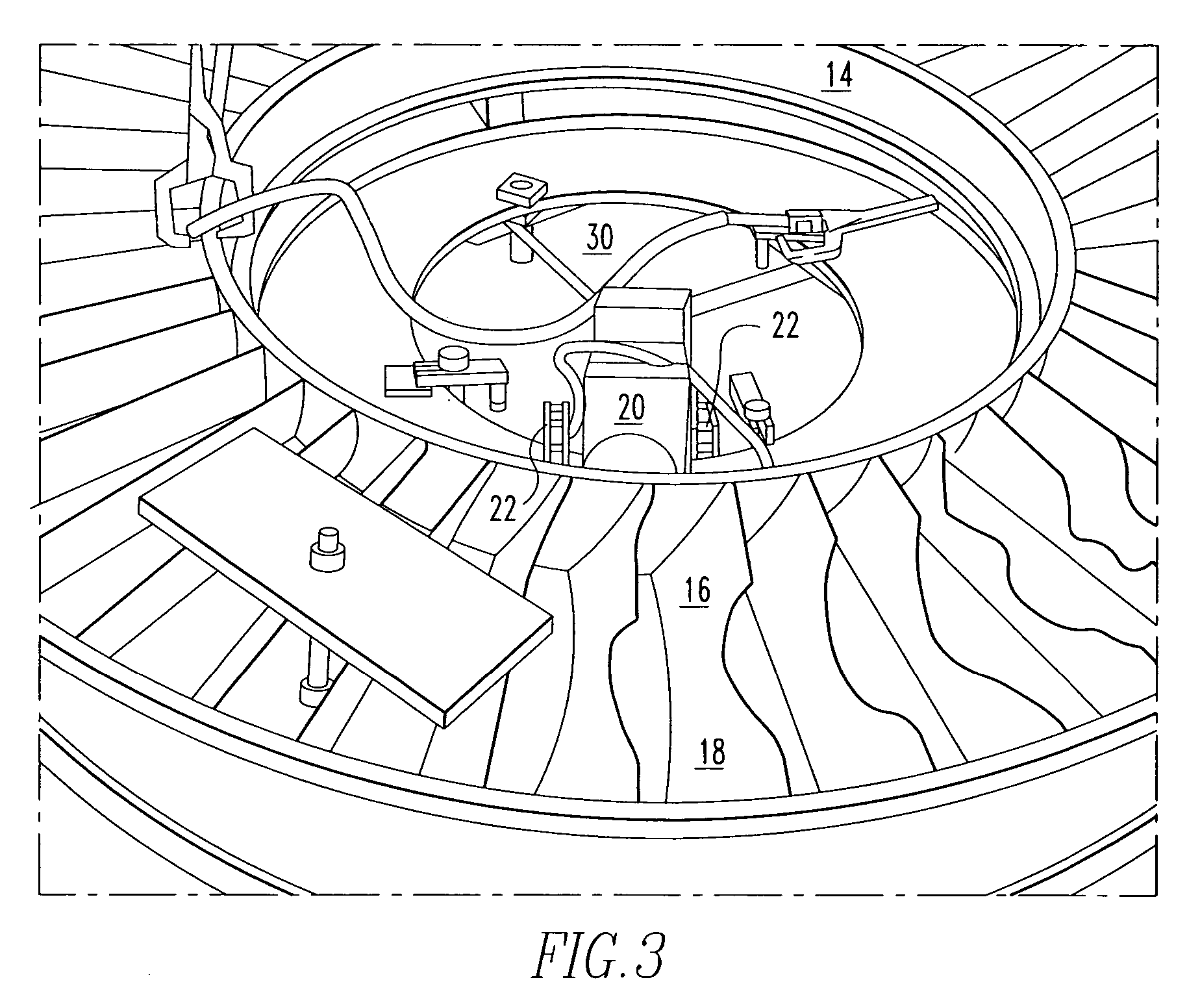
[0020]The component to be repaired is first removed, which in the case of a diaphragm for a turbine may be accomplished by procedures known to those skilled in the art of turbine repair. Referring to FIG. 1, the repair itself may begin by welding a plurality of metal straps 10 between both the inner shroud 12 and mounting plate 14, and the outer shroud 16 and the mounting plate 14. Depending on the structure of the substrate to be welded, and its ability to directly support a force inducer 20 (described below), the mounting plate 14 may or may not be necessary. Preferably, the number of metal straps 10 should not exceed 12, and should be evenly spaced around the inner shroud 12 and outer shroud 16. A preferred number of metal straps 10 may be determined by divid...


PUM

PropertyMeasurementUnit
frequencyaaaaaaaaaa
frequencyaaaaaaaaaa
temperatureaaaaaaaaaa

Abstract

A method of stress relief for stainless steel combustion turbine components includes vibrating the components during welding at a subharmonic frequency. The proper frequency is selected to be below a harmonic frequency, and to produce an amplitude in the range of ¼ to ½ the amplitude produced by a harmonic frequency. The component to be repaired is vibrated during and after welding at this frequency.

Description

BACKGROUND OF THE INVENTION[0001]1. Field of the Invention[0002]The present invention relates to stress reduction during welding. More specifically, the invention provides a method of stress relief wherein the component being welded is vibrated during welding to reduce stresses in the component.[0003]2. Description of the Related Art[0004]Welding is typically used to perform repairs on components of various equipment that is subject to harsh environments. One example is the repair of diaphragm shrouds for a combustion turbine by gas metal arc welding, micro-plasma welding, or gas tungsten arc welding. Such diaphragms are arranged in succession within the compressor of the turbine, with each successive diaphragm having an increasing number of vanes to further compress air being forced into the combustion chamber. Such diaphragms may be exposed to temperatures from room temperature to about 900° F. These diaphragms are difficult to repair, and expensive to replace. Presently available...

Claims


Application Information

Patent Timeline
Patent Type & Authority Patents(United States)
IPC IPC(8): B23K20/10B06B3/02C21D1/04
CPCB23K31/02F01D5/005B23K2201/001F05D2230/232B23K2101/001
Inventor IORDACHE, LUCIANTIMOTIN, OVIDIU
Owner SIEMENS ENERGY INC
Why Eureka
Try Eureka