Optical identification element having non-waveguide photosensitive substrate with diffraction grating therein

a technology of optical identification element and substrate, which is applied in the field of optical identification element having a diffraction grating, can solve the problems of insufficient radio frequency identification, insufficient different codes, and inability to withstand harsh temperature, chemical, nuclear and/or electromagnetic environments, and achieve the effect of increasing photosensitivity and reducing refractive index

Active Publication Date: 2008-10-07
ILLUMINA INC
View PDF421 Cites 29 Cited by
  • Summary
  • Abstract
  • Description
  • Claims
  • Application Information

AI Technical Summary

Benefits of technology

[0019]However, using such a conventional telecommunications waveguide to make such optical identification elements may be expensive to manufacture because the manufacturing techniques for making conventional telecommunications waveguides involve drawing optical fiber from a preform under strict predefined optical conditions so as to produce optical fiber having strict predetermined optical characteristics. Moreover, using such a conventional telecommunications waveguide to make such optical identification elements may also be expensive to manufacture because the manufacturing techniques for making such conventional telecommunications waveguides involving writing strong gratings in the optical fiber with grating writing techniques requiring very precise and expensive lasers in order to meet the demands of the telecommunications industry. In view of this, the inventor has also developed an alternative optical identification element in which a substrate is used such as an optical substrate having the refractive index of the core less than or equal to the cladding, that has important advantages in that it is less expensive to manufacture than when using the conventional waveguide technology otherwise used in the telecommunications industry.
[0022]The microbeads in the alternative embodiment can be manufactured using the same process for inscribing Bragg gratings as those described in some of the above patents. Moreover, due to fact that the beads are interrogated from the side, it is not necessary that the optical substrate be manufactured to perform as a conventional waveguide. It is also well known that the incorporation of Boron as a dopant enhances the photosensitivity of the optical substrate to UV radiation. Boron is also known as an index depressor when it is incorporated into silica glass. When designing a single mode waveguide the amount of Boron is usually very carefully balanced with Germanium to provide the correct index profile in conjunction with enhanced photosensitivity. Again, because the requirement for waveguiding is removed for the microbead applications, excess amounts of Boron can be incorporated into the glass to increase its photosensitivity without regard to its optical guiding properties. This has the benefit of reducing the cost of manufacturing the optical substrate when compared to manufacturing the conventional waveguide, and increasing the photosensitivity without concern for tradeoffs involving other waveguiding issues.
[0029]The elemental (or dopant) constituents (Germanium and Boron dopants) in the core may be about 20 mole % Germanium (Ge) and about 10 mole % Boron (B). Other percentages of the dopants may be used if desired. The Germanium helps increase photosensitivity and the Boron reduces the refractive index to create the depressed core shape of the fiber refractive index profile. Other values of Ge and B may be used provided the inner core region has a refractive index that is less than the outer cladding region (“depressed core”). Also, other dopant(s) now known or later developed may be used to create the depressed core substrate. Also, instead of depressing the refractive index of the core, the refractive index of the cladding may be increased to create the desired depressed core condition. In such a depressed core condition, light will not be guided along the inner core region because it does not satisfy the well known waveguide condition; thus, the substrate does not act as a waveguide. Furthermore, the substrate will not propagate light along the core that could be reflected or diffracted by a diffraction grating located in the substrate.

Problems solved by technology

Existing technologies, such as bar codes, electronic microchips / transponders, radio-frequency identification (RFID), and fluorescence and other optical techniques, are often inadequate.
For example, existing technologies may be too large for certain applications, may not provide enough different codes, or cannot withstand harsh temperature, chemical, nuclear and / or electromagnetic environments.

Method used


Image

  • Optical identification element having non-waveguide photosensitive substrate with diffraction grating therein
  • Optical identification element having non-waveguide photosensitive substrate with diffraction grating therein
  • Optical identification element having non-waveguide photosensitive substrate with diffraction grating therein

Examples


Embodiment Construction

FIG. 1: The Basic Invention

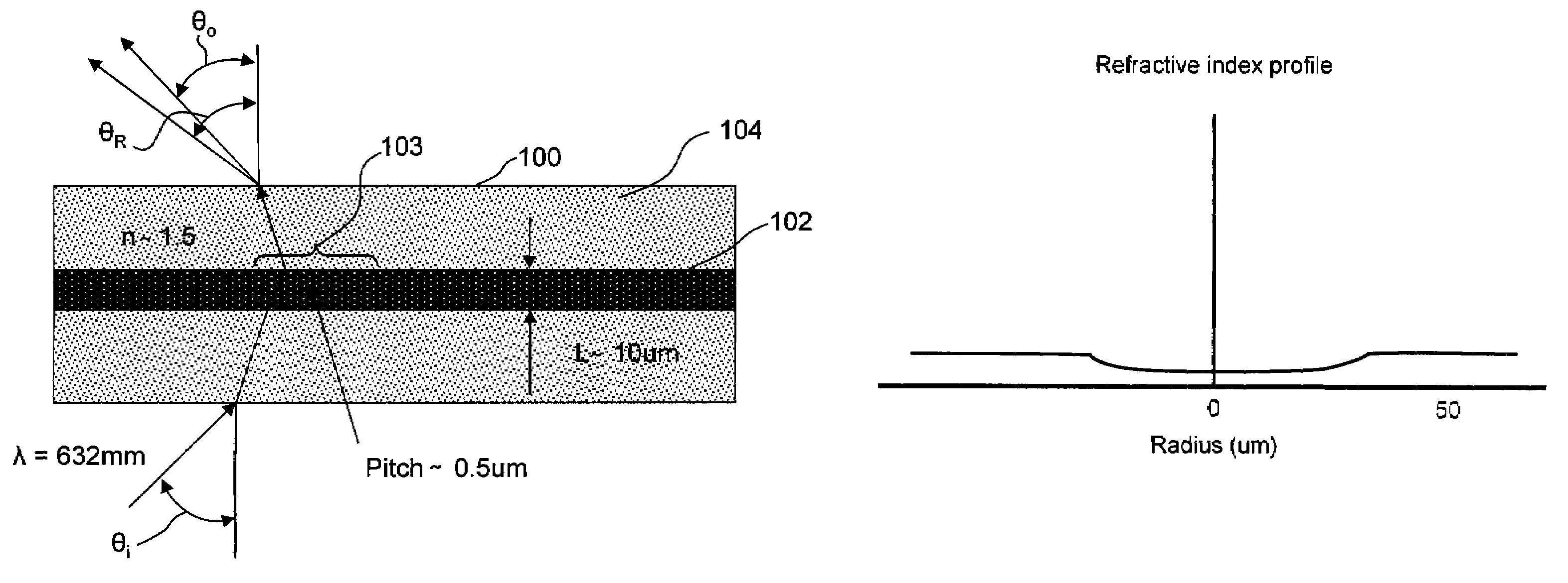
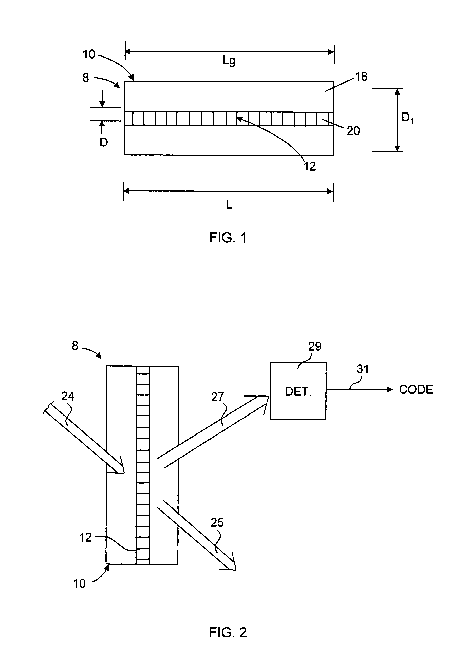
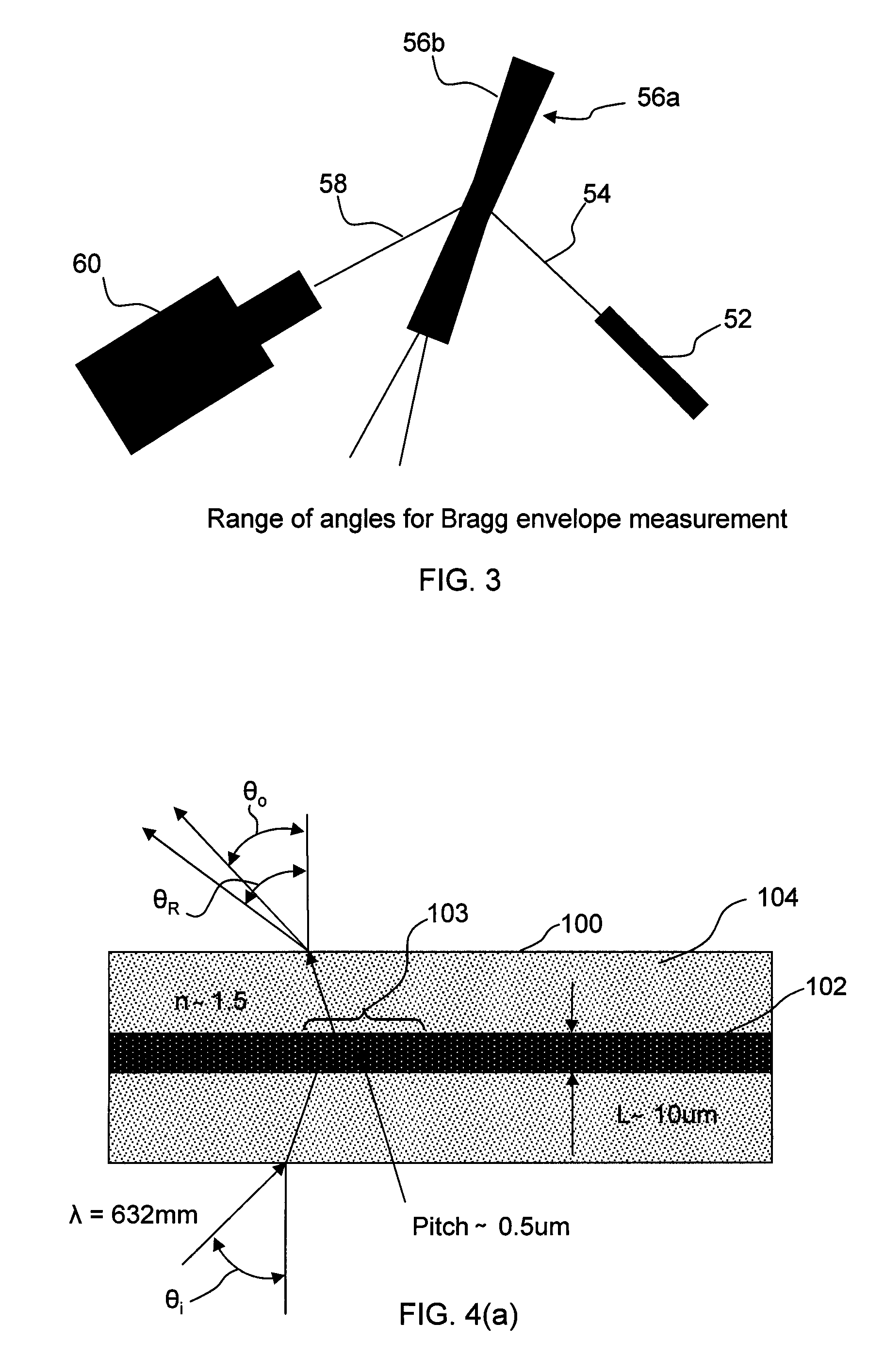
[0044]Referring to FIG. 1, a diffraction grating-based optical identification element 8 (or encoded element or coded element) comprises a known optical substrate 10, having an optical diffraction grating 12 disposed (or written, impressed, embedded, imprinted, etched, grown, deposited or otherwise formed) in the volume of or on a surface of a substrate 10. The optical identification element 8 described herein is the same as that described in Copending patent application Ser. No. 10 / 661,234, filed Sep. 12, 2003, which is incorporated herein by reference in its entirety. The grating 12 may have a periodic or aperiodic variation in the effective refractive index and / or effective optical absorption of at least a portion of the substrate 10. It is important to note that the grating shown and described herein is provided by way of example. The scope of the invention is not intended to be limited to the type or kind of grating 12 in the substrate, the type or kin...


PUM


Abstract

An optical identification element (also known herein as a microbead) that is made from pieces of an optical fiber or substrate that includes an inner core or region being surrounded by an outer cladding region. The optical fiber or substrate has an identification code imparted therein containing coded information. The identification code may be in the form of a Bragg grating inscribed or written in either the inner core or outer cladding. The optical identification element may be microscopic in size having a length in a range of 1-1,000 microns or smaller; or for larger applications may have a length of 1.0-1,000 millimeters or more. The outer diameter may be as small as less than 1,000 microns, as well as in a range of 1.0 to 1,000 millimeters for larger applications.

Description

CROSS REFERENCES TO RELATED APPLICATIONS[0001]This application relates and claims benefit to the following U.S. provisional patent application Ser. No. 60 / 546,445 (CV-0035PR), entitled “Optical Identification Element Having Non-Waveguide Photosensitive Substrate With Bragg Grating Therein”, filed Feb. 19, 2004, which is hereby incorporated by reference in its entirety.[0002]This application also relates to U.S. provisional patent application Ser. Nos. 60 / 546,435 (CV-0053PR), entitled “Multi-Well Plate With Alignment Grooves for Encoded Microparticles”; and 60 / 547,013 (CV-0065PR), entitled “Optical Identification Element Using Separate or Partially Overlapping Diffraction Gratings”, all filed Feb. 19, 2004 and hereby incorporated by reference in their entirety, as well as 11 / 063,665(CV-0053US), entitled “Multi-Well Plate With Alignment Grooves for Encoded Microparticles”, and 11 / 063,666, (CV-0065US), entitled “Optical Identification Element Using Separate or Partially Overlapping Dif...

Claims


Application Information

Patent Timeline
Patent Type & Authority Patents(United States)
IPC IPC(8): G02B5/18G02B6/02G02B6/34G06K19/06
CPCG02B6/021G06K19/06018G06K19/06046
Inventor PUTNAM, MARTIN A.MOON, JOHN A.
Owner ILLUMINA INC
Why Eureka
Try Eureka