
Method and system for measuring the stopping accuracy of an elevator car

a technology for measuring the stopping accuracy and elevator cars, which is applied in the direction of elevators, electric motor speed/torque regulation, hoisting equipment, etc., can solve the problems of inability to integrate monitoring and monitoring systems into elevator systems, inaccuracy of stopping elevator cars, and something wrong with stopping control

Active Publication Date: 2008-10-14
KONE CORP
View PDF11 Cites 8 Cited by
  • Summary
  • Abstract
  • Description
  • Claims
  • Application Information

AI Technical Summary

Benefits of technology

The present invention relates to a condition monitoring method for elevators that measures the stopping accuracy of elevator cars. The invention involves the use of an acceleration sensor on the elevator car and a door zone detector on the floor of the elevator car. The acceleration values measured during the movement of the elevator car are used to calculate the distance of the elevator car to the edge of the door zone. This distance is then used to determine the floor of the elevator car and the time taken to stop. The invention provides a simple and cost-effective solution for monitoring elevator car stopping accuracy. It can also be easily installed and is a self-learning system that learns the distance to a reference point. The invention is separate from the elevator control system, eliminating the need for additional cables and data. The invention also provides a linear location to the edge of the door zone and does not require any on / off-type data to a stopping window set mechanically beforehand.

Problems solved by technology

It is clear that if the floor of the elevator car remains e.g. 15 cm above the floor level, there is something wrong with the control of stopping.
However, not all elevator systems have an integrated system for monitoring the stopping accuracy of the elevator.
Defective operation of the brakes naturally results in an inaccuracy of stopping of the elevator car.
Therefore, magnetic zone measurement does not give any precise information regarding stopping accuracy.
A problem with the use of detectors is that they are very difficult to mount at a precise position.
If the detectors are not mounted at exactly the right positions, then the measurement of stopping accuracy of the elevator car is no longer accurate.
However, such solutions are expensive, and they are not reasonable for mass production in respect of their price / quality ratio.
The problem is that integration is very sensitive to offset-type errors because an error will accumulate over the entire integration cycle.
Especially in double integration, the standard error increases quadratically
An acceleration sensor can never be mounted in a completely straight position, and besides, due to the car load, the acceleration sensor is always somewhat askew.
In addition, electrical resetting of the transducer-amplifier-A / D converter of the chain is never completely free of errors.
If the elevator takes e.g. 4.5 s to travel between successive floors (elevator speed 1 m / s, acceleration 0.8 m / s2, distance between floors 3.2 m), then according to equations (1) and (2) e.g. a 2.5-degree tilt error results in an error of about 10 cm in the position integrated from the acceleration measurement.
This accuracy is not sufficient for the monitoring of stopping accuracy.
In existing elevators with no accurate location system, there is no sufficiently accurate system for monitoring the stopping accuracy of the elevators.
Mechanical basic adjustment and subsequent adjustment / modification of stopping windows is a time-consuming and difficult task.
However, a distributed implementation involves problems:connection to the elevator control panel and finding the correct signals in it and connecting to them, andfor data transfer between the devices in the machine room and on the car top, an extra car cable has to be installed.
Based on the circumstances described above, there are considerable drawbacks in present-day condition monitoring systems in existing elevators, especially in respect of measurement and monitoring of stopping accuracy.

Method used


Image

  • Method and system for measuring the stopping accuracy of an elevator car
  • Method and system for measuring the stopping accuracy of an elevator car
  • Method and system for measuring the stopping accuracy of an elevator car

Examples


Embodiment Construction

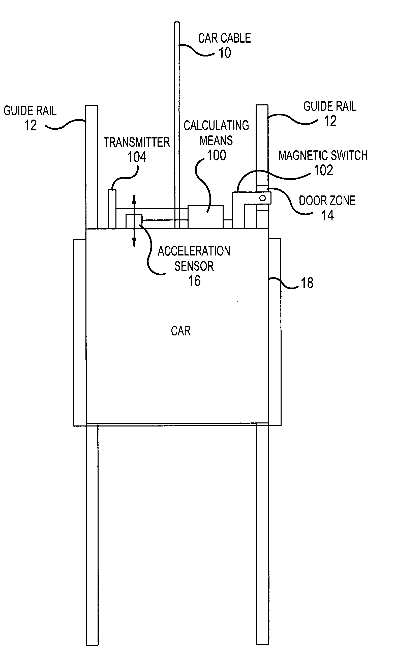
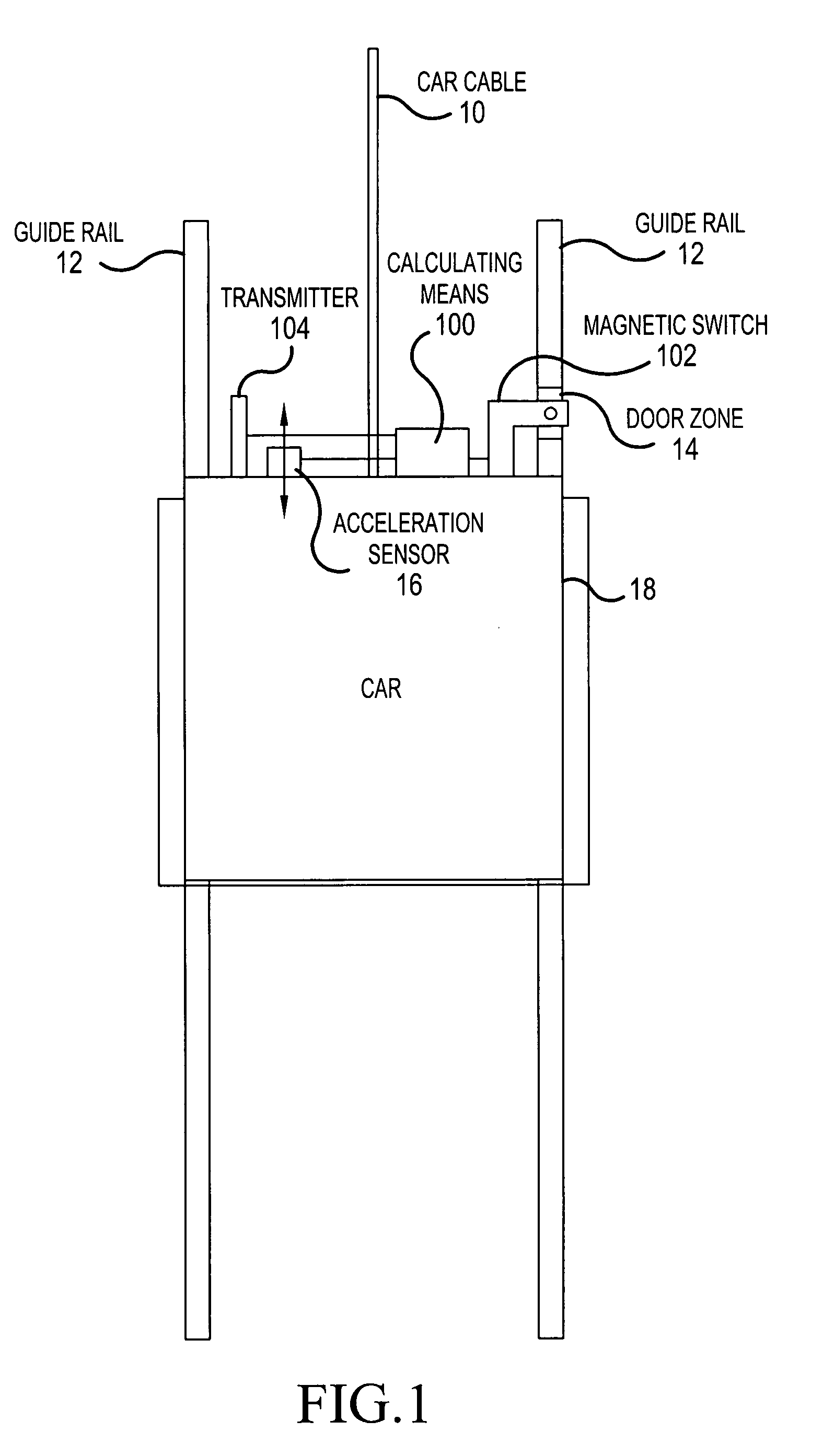
[0042]FIG. 1 presents an elevator system according to the invention. An elevator car 18 controlled by a car cable 10 moves along guide rails 12. Installed on the elevator car 18 is an acceleration sensor 16, which is used to measure vertical acceleration of the elevator car 18. The acceleration sensor 16 can be installed on the elevator car 18 expressly for an embodiment of the invention or alternatively the invention can be implemented utilizing an acceleration sensor already existing on the elevator car. In addition, arranged on or near the elevator car 18 are calculating means 100 for the calculation of the distance of the elevator car from the edge of the door zone on the basis of the measured acceleration values. The calculating means 100 are implemented using e.g. a processor and a memory arranged in connection with it or completely via software.

[0043]At every floor, a device or arrangement indicating a door zone 14 is installed. The door zone 14 can be E.g. marked by upper an...


PUM


Abstract

The invention relates to a condition monitoring method and a corresponding system for measuring the stopping accuracy of an elevator car. In the invention, a door zone is defined for each floor, a door zone detector is mounted on the elevator car, the elevator car is moved towards a destination floor, acceleration values of the elevator car are measured during its travel towards the destination floor by means of an acceleration sensor attached to the elevator car and the distance of the stopped elevator from the edge of the door zone is calculated on the basis of the measured acceleration values.

Description

[0001]This application is a Continuation of co-pending PCT International Application No. PCT / FI2005 / 000401 filed on Sep. 22, 2005, which designated the United States, and on which priority is claimed under 35 U.S.C. § 120. This application also claims priority under 35 U.S.C. § 119(a) on Patent Application No(s). 20041241 filed in Finland on Sep. 27, 2004. The entire contents of each of the above documents is hereby incorporated by reference.FIELD OF THE INVENTION[0002]The present invention relates to elevator systems. In particular, the present invention concerns a method and a system for measuring the stopping accuracy of an elevator car for condition monitoring.BACKGROUND OF THE INVENTION[0003]For practical operation of elevator systems, it is important that the elevator car should stop at the desired position at a floor. In other words, the stopping accuracy of the elevator car has to be within a certain tolerance. It is clear that if the floor of the elevator car remains e.g. 1...

Claims


Application Information

Patent Timeline
Patent Type & Authority Patents(United States)
IPC IPC(8): B66B1/34B66BB66B1/40
CPCB66B1/40
Inventor TYNI, TAPIOPERALLA, PEKKA
Owner KONE CORP
Learn More