Packaging of microfluidic devices

a microfluidic device and packaging technology, applied in the field of microfluidic devices, can solve the problems of inability to meet the needs of laboratory glassware, inability to accurately measure, and inability to migrate from the chamber, and achieve the effects of limiting moisture transfer, low affinity, and prolonging the shelf life of the devi

Active Publication Date: 2008-10-14
SIEMENS HEALTHCARE DIAGNOSTICS INC
View PDF166 Cites 61 Cited by
  • Summary
  • Abstract
  • Description
  • Claims
  • Application Information

AI Technical Summary

Benefits of technology

[0010]In a further aspect, the invention is a microfluidic device in which the materials used to make the device prevent transfer of moisture in or out of the device to a rate within 0.01 g/m2/day or less to extend the shelf life of the device. Plastics having a suitably low affinity for moisture are used in thickness capable of limiting moisture transfer to the desired amount. In a preferred embodiment, the base of the dev

Problems solved by technology

However, loading the microfluidic device manually with very small amounts of reagents may be difficult to do with precision and could lead to in

Method used


Image

  • Packaging of microfluidic devices
  • Packaging of microfluidic devices

Examples


Embodiment Construction

General Description of Microfluidic Devices

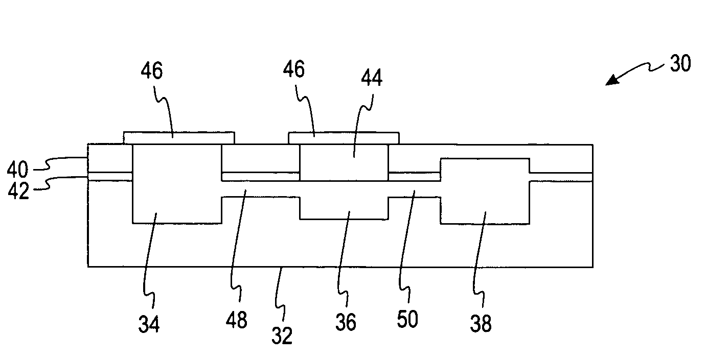
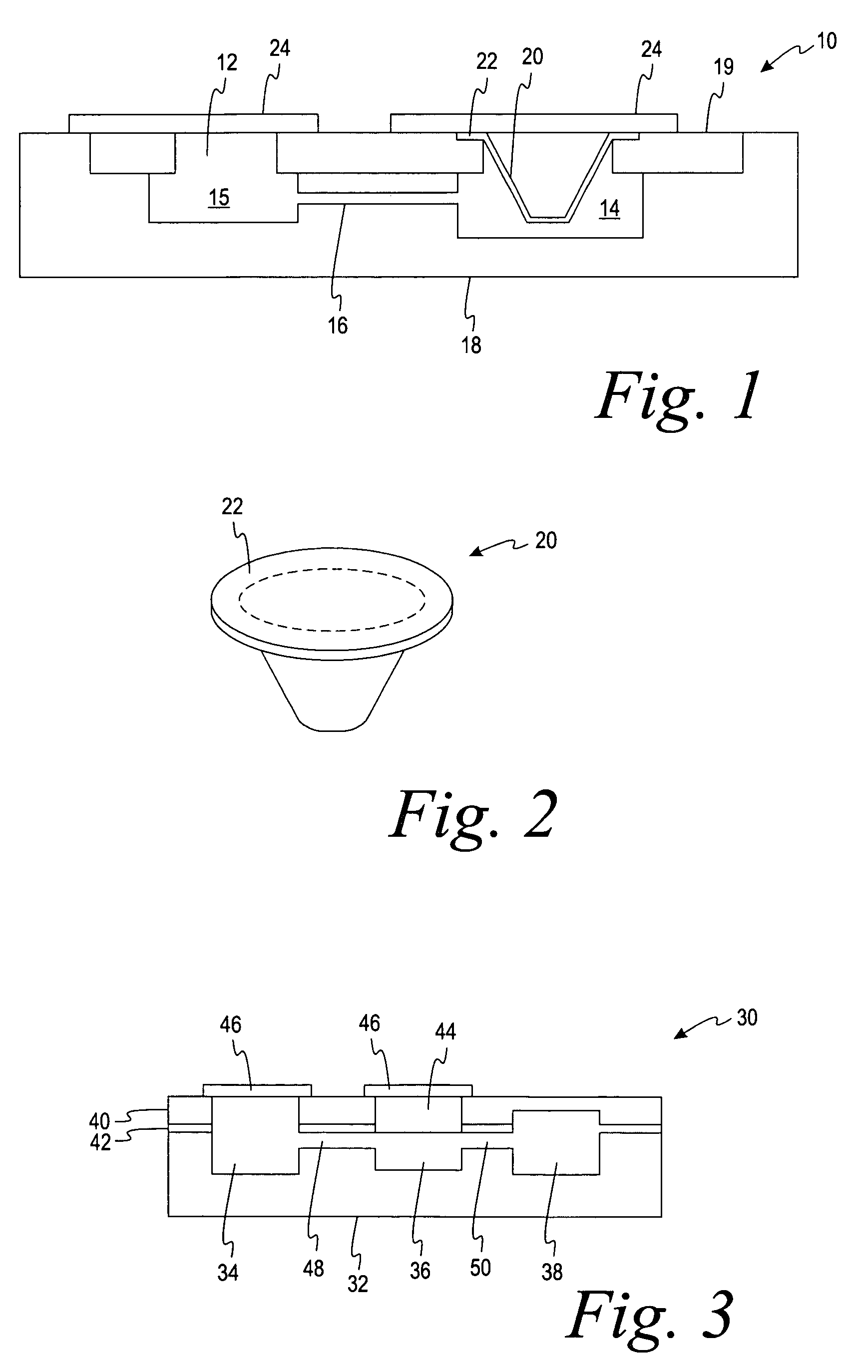
[0014]Microfluidic devices sometimes are referred to as “chips”. They are generally small and flat, typically about 1 to 2 inches square (25 to 50 mm square) or circular discs of similar size (e.g., 25 to 120 mm radius). The volume of samples supplied to the microfluidic chips are typically small, i.e., about 0.3 to 5 μL. The sample liquids are moved through a series of chambers interconnected by capillary passageways having widths in the range of 10 to 500 μm, preferably 20 to 100 μm. The minimum permitted depth of the passageways may be determined by the properties of the sample. For example, the depth typically will be at least 5 μm, but at least 20 μm when whole blood is the sample.

[0015]While there are several ways in which the capillaries and sample wells can be formed, such as injection molding, laser ablation, diamond milling or embossing. It is preferred to use injection molding in order to minimize cost while reproducing structura...


PUM

PropertyMeasurementUnit
Thicknessaaaaaaaaaa
Massaaaaaaaaaa
Fractionaaaaaaaaaa

Abstract

A microfluidic device containing liquid reagents having an extended shelf life contains the liquid reagents in micro-reservoirs that limit the escape of moisture to less than 10% over the shelf life of the device. The micro-reservoir preferably is made of polypropylene and covered with a metallized plastic film.

Description

BACKGROUND OF THE INVENTION[0001]This invention relates to microfluidic devices that as can be used for carrying out analysis of biological samples, such as blood, urine and the like. More particularly, the invention relates to the materials for such devices and to their construction.[0002]Microfluidic devices have been the subject of many patents and patent applications. The general principles of microfluidic devices of the present invention have been discussed in U.S. patent application Ser. No. 10 / 082,415 and more specific features of such devices are the subject of other applications. Such microfluidic devices include very small chambers containing liquid or solid reagents which contact liquid samples as they move through the device via capillary passageways, typically by capillary forces or applied centrifugal force (although other means of moving liquid have been disclosed and could be used in some microfluidic devices). After a small sample of liquid is added, the desired qua...

Claims


Application Information

Patent Timeline
IPC IPC(8): G01N33/48B01L3/00
CPCB01L3/502707B01L2200/142B01L2200/16B01L2300/0672B01L2400/0406B01L2400/0677B01L2400/0683B29K2509/08
Inventor PUGIA, MICHAEL J.PROFITT, JAMES A.SOMMER, RONALD G.JUNG, SUNG-KWON
Owner SIEMENS HEALTHCARE DIAGNOSTICS INC
Why Eureka
Try Eureka