Signal transmission structure, circuit board and connector assembly structure

a technology of signal transmission and circuit board, applied in the direction of waveguide type devices, fixed connections, coupling devices, etc., can solve the problems of increasing insertion loss and affecting signal transmission quality, and achieve the effects of improving signal transmission quality, improving impedance continuity, and reducing capacitan

Active Publication Date: 2008-10-14
VIA TECH INC
View PDF1 Cites 3 Cited by
  • Summary
  • Abstract
  • Description
  • Claims
  • Application Information

AI Technical Summary

Benefits of technology

[0009]The objective of the present invention is providing a signal transmission structure for increasing the signal transmission impedance continuity.
[0010]Another objective of the present invention is providing a circuit board for improving the impedance continuity in the signal transmission path.
[0011]Another objective of the present invention is providing a connector assembly structure for improving the impedance continuity in the signal transmission path for the circuit board.
[0024]Based on the above examples, the present invention uses the compensation pad for connecting between the first line segment and the second line segment, and the parasitic capacitance caused by the compensation pad and the first reference plane can be used for improving impedance continuity from the signal perforated pad to the second line segment. Therefore, the signal transmission structure, circuit board, and connector assembly structure according to the present invention can improve signal transmission quality.
[0025]Furthermore, the present invention can use the open space region and the compensation region for reducing the capacitance between the signal perforated pad with the first line segment and the first reference plane, and further improving the impedance continuity from the signal perforated pad to the second line segment. In addition, the present invention can use the first line segment in a non-straight line design for increasing the inductance between the first line segment and the first reference plane, and for increasing the impedance continuity between the signal perforated pad and the second line segment.

Problems solved by technology

In the conventional signal transmission structure 100, the characteristic impedance of the signal perforated pad 112 is less than that of the first line segment 114; and the difference of characteristic impedance between the two is dramatic, which leads to increasing of insertion loss during signal transmission, thus affecting signal transmission quality especially during high frequency transmission.

Method used


Image

  • Signal transmission structure, circuit board and connector assembly structure
  • Signal transmission structure, circuit board and connector assembly structure
  • Signal transmission structure, circuit board and connector assembly structure

Examples


first embodiment

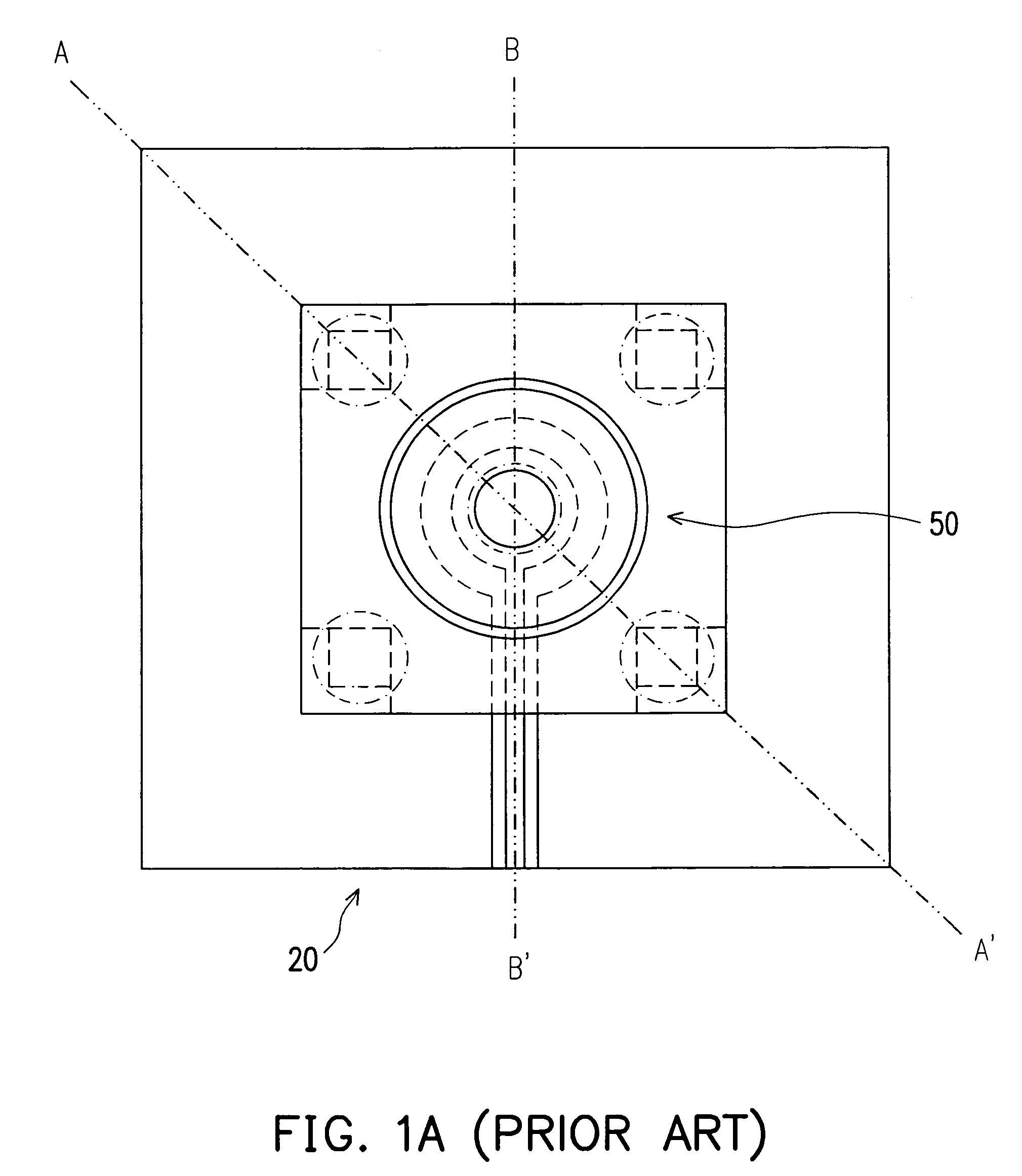
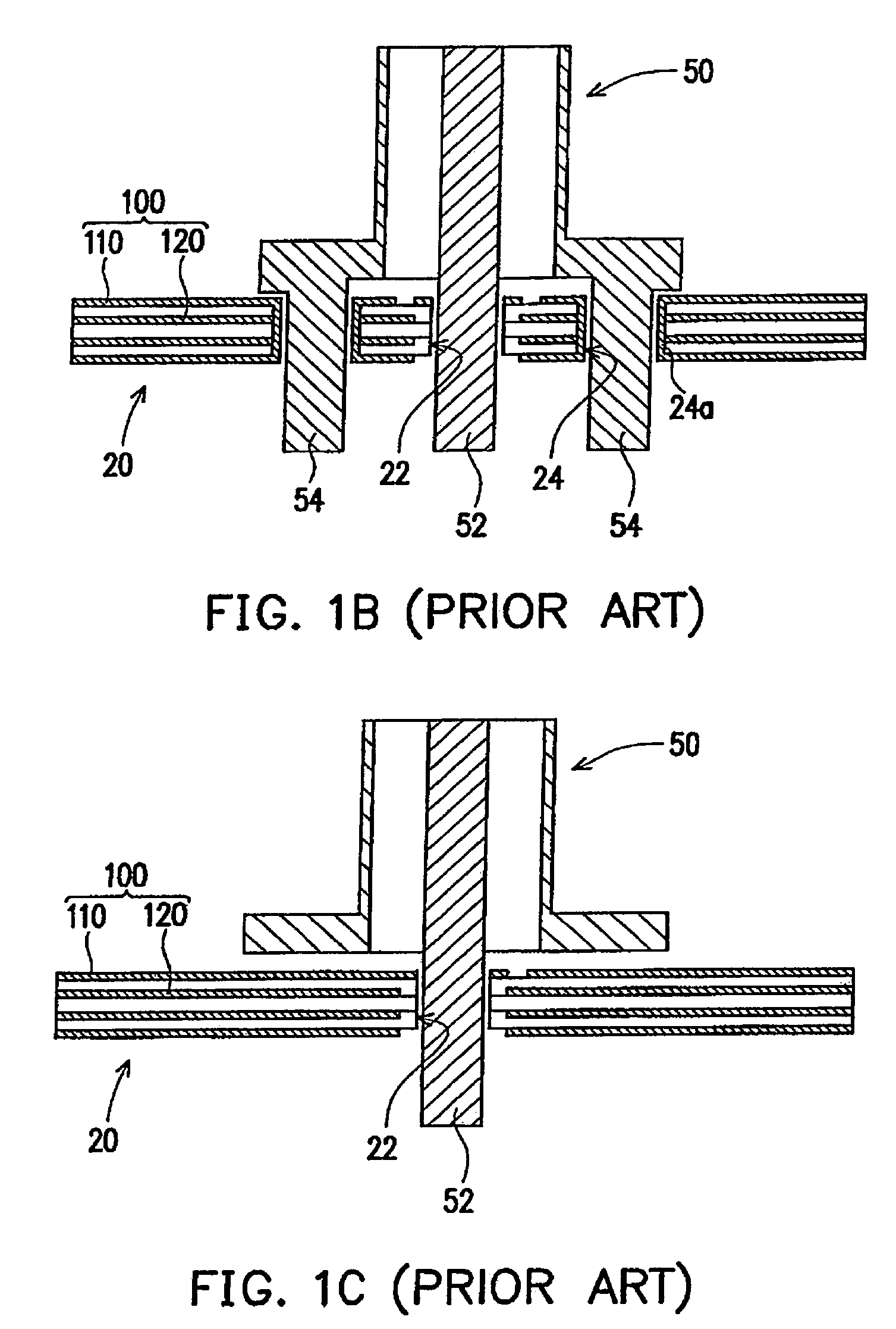
[0037]FIG. 2A is a top view of a signal transmission structure according to an embodiment of the present invention, FIG. 2B and FIG. 2C are top views for individually illustrating the conductive layer and the first reference plane of the first embodiment. Whereas, FIG. 3 illustrates a cross-sectional view of signal transmission structure in FIG. 2A connecting with a connector. In reference to FIG. 2A to FIG. 2C and FIG. 3, FIG. 3 illustrates the signal transmission structure with the cross-sectional views through line I-I′ in FIG. 2A. A signal transmission structure 200a of the embodiment of the present invention is suitable for connecting to a coaxial cable connector, in which the coaxial cable connector is an upright SMA connector 50 that includes a signal pin 52 and a plurality of alignment pins 54. The signal transmission structure 200a that is disposed at a circuit board 20 includes a conductive layer 210a and a first reference plane 220a. Whereas the conductive layer 210a and ...

second embodiment

[0041]FIG. 4A schematically illustrates a top view of a signal transmission structure, according to a second embodiment of the present invention. FIG. 4B and FIG. 4C respectively illustrates a top view of FIG. 4A at the conductive layer and the first reference plane. Referring to FIG. 4A to FIG. 4C, the present embodiment signal transmission structure 200b of the embodiment is similar to the signal transmission structure 200a (as shown in FIG. 2A). However, the differences are found at the conductive layer 210b of the signal transmission structure 200b having a second reference plane 218, and surrounding the signal perforated pad 212, the first line segment 213, the compensation pad 215, and the second line segment 214. The above described first alignment perforated pad 216 is, for example, constructed from a plurality of sections from the second reference plane 218. Furthermore, the second reference plane 218 can be a ground plane or a power plane.

third embodiment

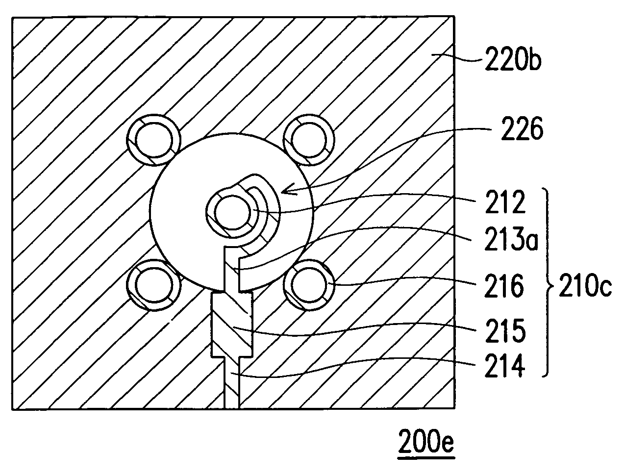
[0042]FIG. 5A and FIG. 5B respectively illustrates a top view of the two signal transmission structures according to the third embodiment of the present invention. In reference to FIG. 5A, because it is similar to the first embodiment shown in FIG. 2A, only the differences are described. The first reference plane 220b of the signal transmission structure 200c in the embodiment includes an open space region 226. The open space region 226 is the non-conducting region of the first reference plane 220b. The projection of the signal perforated pad 212 and the first line segment 213 at the first reference plane 220b is located within the open space region 226.

[0043]In other words, the present embodiment can enlarge the insulating opening 224 of the first reference plane 220b (as shown in FIG. 2C) to form the open space region 226. As a result, it can reduce the capacitance between the signal perforated pad 212 with the first line segment 213 and the first reference plane 220c, and further...


PUM


Abstract

A signal transmission structure for connecting a coaxial cable connector is provided. The coaxial cable connector has a signal pin. The signal transmission structure includes a reference plane and a conductive layer, and the conductive layer is located on one side of the reference plane. Moreover, the conductive layer includes a signal perforated pad, a first line segment, a second line segment, and a compensation pad. The signal pin is suitable for threading the signal perforated pad. The first line segment is connected to the signal perforated pad, and the compensation pad is connected between the first line segment and the second line segment.

Description

CROSS-REFERENCE TO RELATED APPLICATION[0001]This application claims the priority benefit of Taiwan application serial no. TW94113067, filed on Apr. 24, 2005. All disclosure of the Taiwan application is incorporated herein by reference.BACKGROUND OF THE INVENTION[0002]1. Field of Invention[0003]The present invention relates to a signal transmission structure, circuit board, and connector assembly structure. More particularly, it relates to a signal transmission structure, circuit board, and a connector assembly structure with increased impedance continuity on a signal transmission path.[0004]2. Description of Related Art[0005]For large-scale printed circuit board and packaging substrate having electrical connections for signal lines between two elements or terminals, the wire width in the signal line has to be consistent. Thus, during electronic signal transmission, the characteristic impedance of the signal wire can remain the same. Especially during high speed and high frequency si...

Claims


Application Information

Patent Timeline
Patent Type & Authority Patents(United States)
IPC IPC(8): H03H7/38
CPCH01R12/58H01R24/50H05K1/0243H01R2103/00H05K1/0219H05K1/0222H05K1/116H05K3/3447H05K3/429H05K2201/09281H05K2201/09618H05K2201/09727H05K2201/09809H05K2201/10189H01R12/7064
Inventor JIANG, SHIN-SHINGLEE, SHENG-YUAN
Owner VIA TECH INC
Why Eureka
Try Eureka