
Dark field inspection apparatus and methods

a technology for specimen inspection and apparatus, applied in the direction of instruments, measurement devices, scientific instruments, etc., can solve the problems of affecting the darkfield inspection, scattered light, scattered light, etc., and achieve the effect of reducing or eliminating the long range ringing respons

Active Publication Date: 2008-10-14
KLA TENCOR TECH CORP
View PDF7 Cites 36 Cited by
  • Summary
  • Abstract
  • Description
  • Claims
  • Application Information

AI Technical Summary

Benefits of technology

[0011]Accordingly, the present invention provides methods and apparatus for performing a darkfield inspection on a specimen having periodic structures thereon while substantially reducing or eliminating the long range ringing response that was typically produced by the traditional Fourier filter masks used to remove the signature caused by the periodic structures.
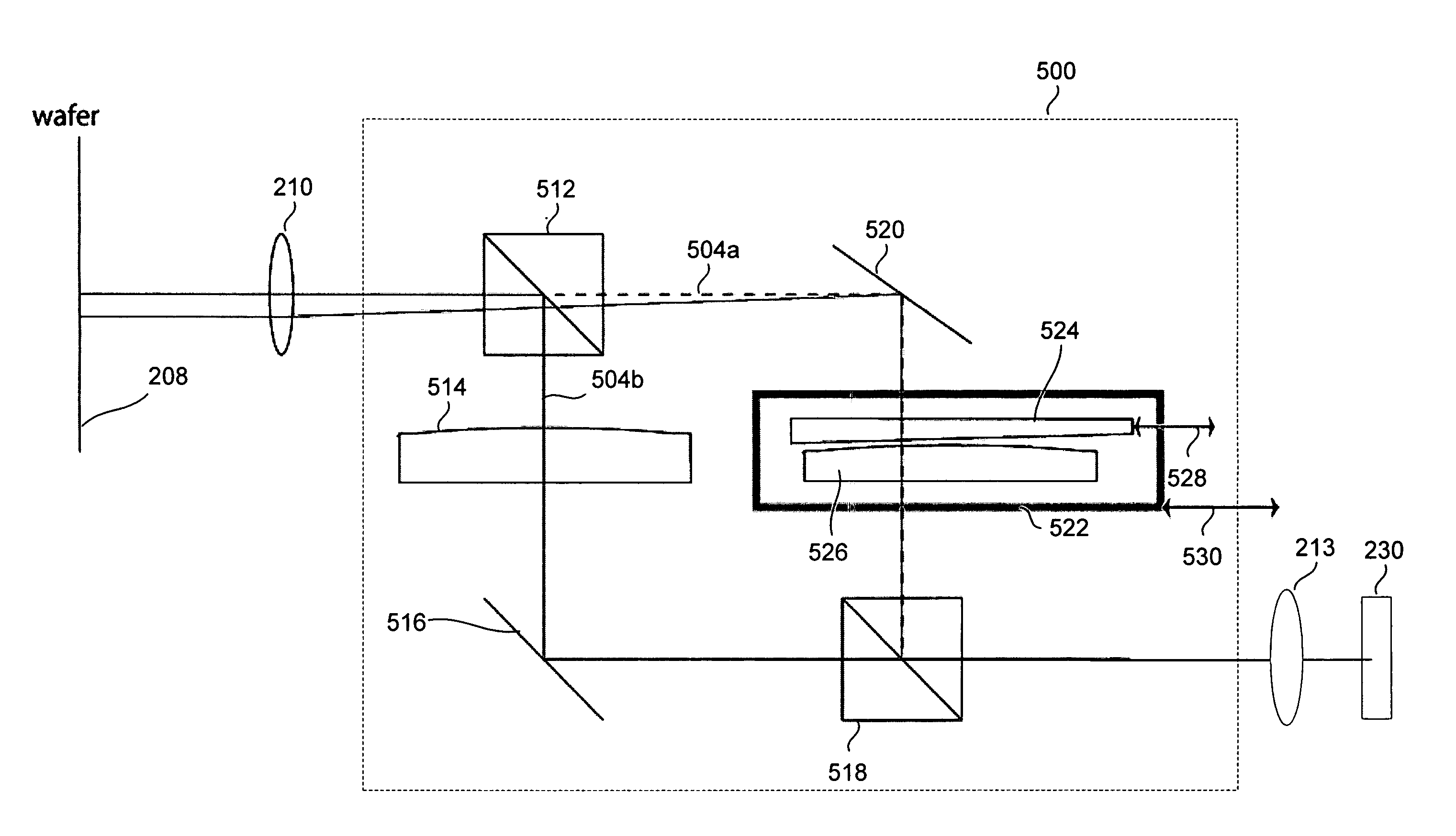
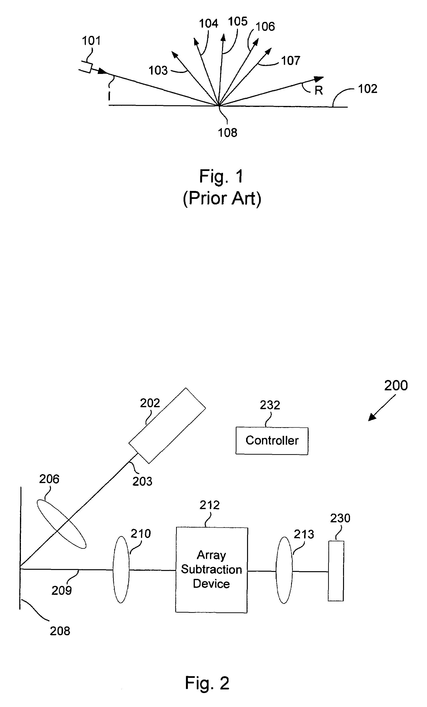
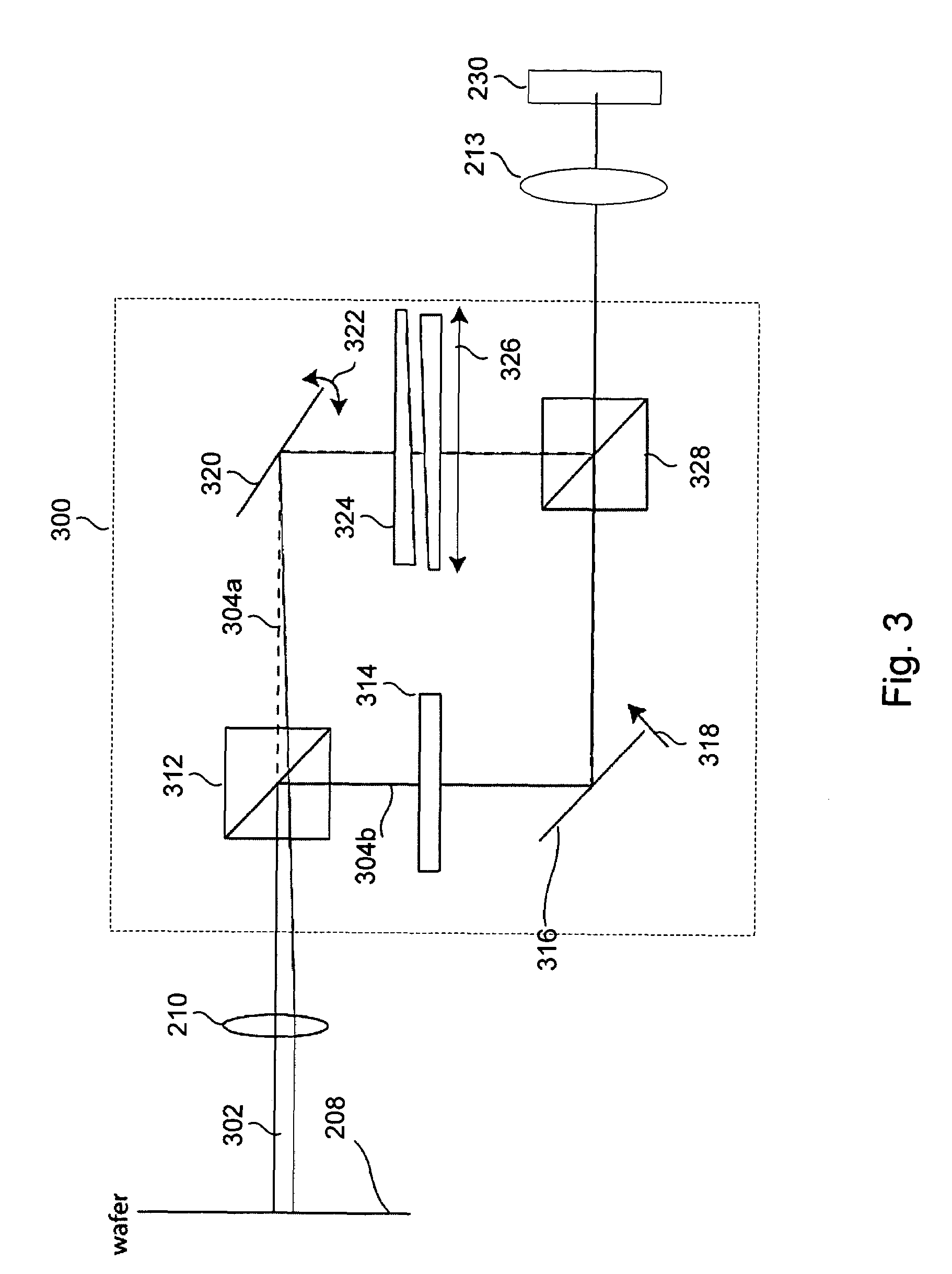
[0012]In one embodiment, an apparatus for inspecting a specimen by detecting optical beams scattered from the specimen. The apparatus includes a beam generator for providing and directing an incident beam towards a specimen and an array subtraction device for substantially subtracting a periodic component from an output beam scattered from the specimen in response to the incident beam. The periodic component corresponds to at least one periodic structure on the specimen, and the subtraction is performed so as to substantially reduce or eliminate a ringing response from the output beam. The subtraction is also performed so as to substantially prevent subtracting any actual defect components from the output beam. The apparatus further includes a detector for receiving the output beam and generating an output image or signal based on the output beam. In a further aspect, the apparatus also includes a controller for analyzing the output image or signal to determine whether there are any defects present on the specimen.
[0013]In a specific implementation, the array subtraction device is formed from a splitter for receiving the output beam before it reaches the detector and splitting the output beam into a first and a second secondary beam which are output from the splitter and a phase and pitch adjuster for receiving the first secondary beam, wherein the phase and pitch adjuster is configured to spatially shift the first secondary beam relative to the second secondary beam by an integer amount of a period of the periodic structure and reverse the polarity of the first or second secondary beam. In this implementation, the array subtraction device further includes a combiner for receiving the first secondary beam after it passes through the phase and pitch adjuster and for receiving the second secondary beam. The combiner is configured to combine the first and second secondary beams so that the periodic component is substantially subtracted from the combined output beam so as to substantially reduce or eliminate a ringing response and to substantially prevent subtracting any actual defect components from the combined output beam.
[0018]In another embodiment, the array subtraction device is formed from a spatial light modulator (SLM) positioned in the Fourier plane of the output beam and configured to substantially block the periodic component from the output beam while substantially reducing or eliminating the ringing response. In a further aspect, the SLM is configured with an amplitude profile that has a sinusoidal shape, where the profile is zero or crosses zero at the center of each diffraction peak produced by the periodic component. In another aspect, the SLM is configured so as to substantially block each diffraction peak of the periodic component and to partially and gradually block the remaining edge portions of each peak. In yet another aspect, the SLM is configured with varying transmission levels in positions that correspond to diffraction peaks of the periodic component so as to smoothly reduce an amplitude at the edges of the peaks. The array subtraction device may further include an aperture positioned at the Fourier plane to completely block areas outside a boundary of the diffraction pattern outer edge of the periodic component so as to minimize ringing at such edge.

Problems solved by technology

When a specimen contains periodic structures, such as semiconductor devices on a wafer, these periodic or “array” structures tend to adversely affect the darkfield inspection results.
Although these periodic structures are not considered to be defects, these structures result in scattered light during the darkfield inspection.
Since the defects also result in scattered light, the scattered light from the actual defect is not easily distinguishable from the scattered light from the periodic non-defect structures.
Thus, the periodic structures contribute noise to the scattered light from the specimen, which is analyzed for defects.
Although conventional masks for blocking diffraction peaks from periodic structure are effective and leave no adverse side effects for the non-imaging darkfield system, they have several disadvantages for the imaging darkfield system.
One problem with a physical blockage type filter for the imaging darkfield system is that the optical response of the physical mask contains significant numbers of side lobes which can extend to 100 um, also referred herein as a “long range ringing response.” There are two major problems with this long range ringing response.
The light in the bus regions leak into the array region, reducing the array region defect sensitivity.
Second, the long-ranged ringing response couples the noise in the bus regions with the noise in the array regions.
This is highly undesirable because this kind of noise coupling cannot be well characterized, adding uncertainty to the performance of the system.

Method used


Image

  • Dark field inspection apparatus and methods
  • Dark field inspection apparatus and methods
  • Dark field inspection apparatus and methods

Examples


Embodiment Construction

[0030]Reference will now be made in detail to a specific embodiment of the invention. An example of this embodiment is illustrated in the accompanying drawings. While the invention will be described in conjunction with this specific embodiment, it will be understood that it is not intended to limit the invention to one embodiment. On the contrary, it is intended to cover alternatives, modifications, and equivalents as may be included within the spirit and scope of the invention as defined by the appended claims. In the following description, numerous specific details are set forth in order to provide a thorough understanding of the present invention. The present invention may be practiced without some or all of these specific details. In other instances, well known process operations have not been described in detail in order not to unnecessarily obscure the present invention.

[0031]In general, the present invention includes array suppression mechanisms that are arranged in the outpu...


PUM


Abstract

Accordingly, the present invention provides methods and apparatus for performing a darkfield inspection on a specimen having periodic structures thereon while substantially reducing or eliminating the long range ringing response, which is typically produced by a traditional Fourier filter mask used to eliminate the diffraction caused by the periodic structures. In one embodiment, an apparatus for inspecting a specimen by detecting optical beams scattered from the specimen. The apparatus includes a beam generator for providing and directing an incident beam towards a specimen and an array subtraction device for substantially subtracting a periodic component from an output beam scattered from the specimen in response to the incident beam. The periodic component corresponds to at least one periodic structure on the specimen, and the subtraction is performed so as to substantially reduce or eliminate a ringing response from the output beam. The subtraction is also performed so as to substantially prevent subtracting any actual defect components from the output beam. The apparatus further includes a detector for receiving the output beam and generating an output image or signal based on the output beam.

Description

CROSS REFERENCE TO RELATED PATENT APPLICATION[0001]This application claims priority of U.S. Provisional Application No. 60 / 598,799 filed on Aug. 3, 2004 entitled DARK FIELD INSPECTION APPARATUS AND METHODS, by Chen, et al. which is incorporated herein by reference in its entirety for all purposes.BACKGROUND OF THE INVENTION[0002]This invention pertains to apparatus and methods for inspecting a specimen, such as a semiconductor wafer or photomask in a dark field inspection system or the like. It also pertains to apparatus and methods for reducing or eliminating from the inspection results the effects contributed by periodic structures on the specimen.[0003]A diverse number and type of inspection systems are available for inspecting samples for defects. One inspection type is referred to as a “darkfield” inspection. Darkfield inspection makes use of light scattered or diffracted by the surface to characterize and examine features of the surface. As used herein, scattered light shall r...

Claims


Application Information

Patent Timeline
IPC IPC(8): G01N21/00G02B27/42
CPCG01N21/9501G02B21/10G01N2021/9563
Inventor CHEN, GRACE HSIU-LINGFU, TAO-YIMAPOLES, EVAN
Owner KLA TENCOR TECH CORP
Learn More