
Actuator operated microvalves

a micro-actuator and actuator technology, applied in the direction of non-mechanical valves, valve details, valve arrangements, etc., can solve the problems of limited temperature operation of conventional semiconductor electronic and sensing devices, and achieve the effect of reducing the per unit cost of the actuator and excellent high temperature properties of the materials used

Inactive Publication Date: 2008-10-21
NASA
View PDF41 Cites 21 Cited by
  • Summary
  • Abstract
  • Description
  • Claims
  • Application Information

AI Technical Summary

Benefits of technology

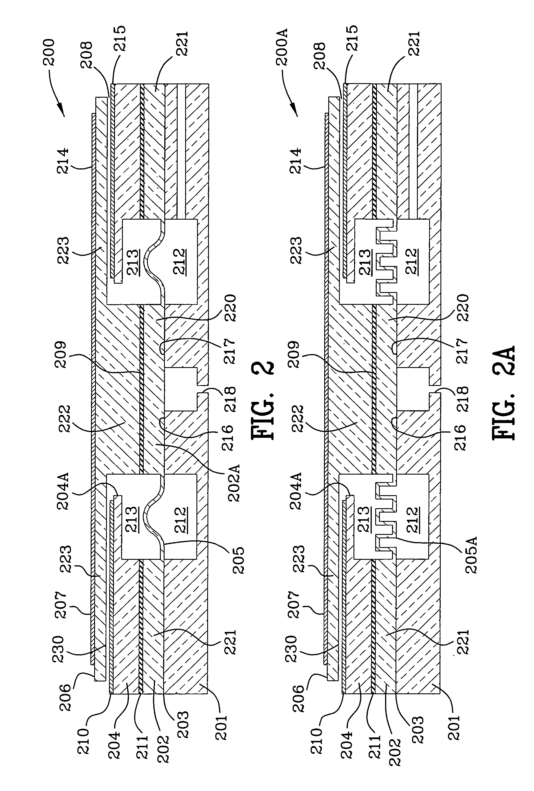
[0020]The first electrode is preferably a nickel plate affixed to the top plate and the second electrode is preferably a nickel plate. The first electrode is the anode and the second electrode is the cathode. Alternatively the SiC top plate is heavily doped to be conductive and the doped top plate constitutes the first electrode. The SiC top plate includes a cylindrical portion and an insulator is affixed to the boss of the diaphragm and the cylindrical portion of the top plate to provide electrical isolation.
[0037]The actuator operated microvalve is developed for insertion or embedding, partially or wholly, in the flow field of a flow channel for the purpose of controlling and modulating the flow of liquid or gas. The actuator operated microvalve provides minimum intrusion in the flow field while at the same time significantly effects the profile of the flow. The actuator operated microvalve provides reasonable valve travel that permits the control and manipulation of flow rates over a wide range. Actuation can be implemented by applying electrostatic, electromagnetic, piezoelectric or electrokinetic principles, although the preferred actuation is electrostatic. To prevent premature fuel ignition and dangerous explosions, the actuation mechanism provides electrical isolation between the fuel path and the actuating electrodes.

Problems solved by technology

This is very challenging since conventional semiconductor electronic and sensing devices are limited to operating in temperatures less than 300° C. due to the limitations imposed by material properties and packaging.

Method used


Image

  • Actuator operated microvalves
  • Actuator operated microvalves
  • Actuator operated microvalves

Examples


Embodiment Construction

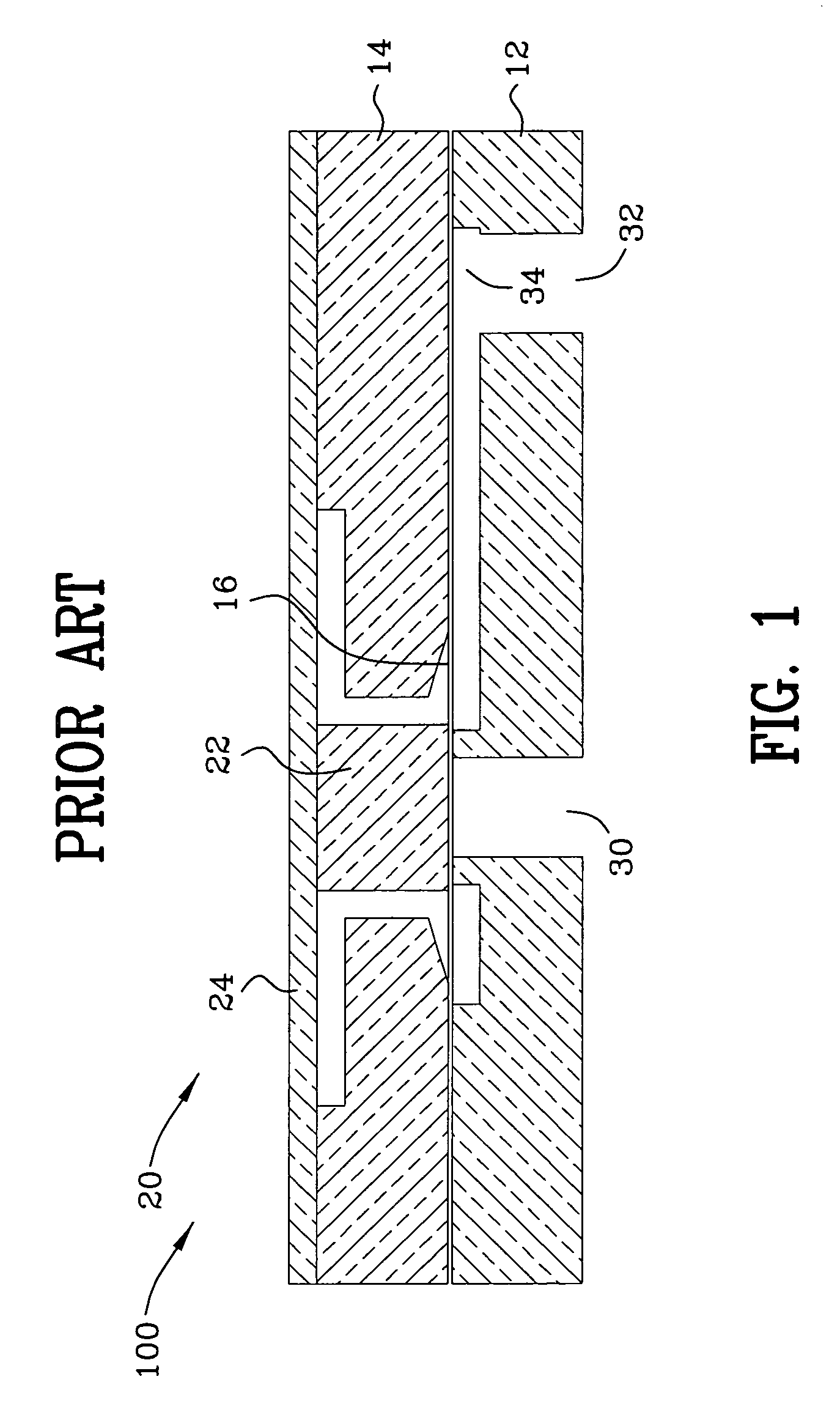
[0096]FIG. 1 is a cross-sectional view 100 of a drawing FIG. 3 from U.S. Pat. No. 6,774,337. Also, U.S. Pat. No. 6,883,774 B2 illustrates in FIG. 3 thereof the same drawing in a less clear fashion. U.S. Pat. No. 6,883,774 B2 to Nielsen et al. entitled Microelectromechanical High Pressure Microvalve discloses first and second layers (12, 14) of SiC or Si, a stainless steel diaphragm member 16, boss 22 and switching means 20. The microvalve is designed for high pressure applications and employs a thin metallic diaphragm sandwiched between first and second layers of SiC or Si. The cracking pressure at which the stainless steel diaphragm opens is approximately 800 psi and the microvalve may be modified to open at pressures from 800-1200 psi. The diaphragm is biased in the closed position and moves from the closed position to the open position when the pressure of fluid in the inlet reaches a preset value. The switching means is connected to the valve body for moving the diaphragm to the...


PUM


Abstract

An actuator operated microvalve and the method of making same is disclosed and claimed. The microvalve comprises a SiC housing which includes a first lower portion and a second upper portion. The lower portion of the SiC housing includes a passageway therethrough, a microvalve seat, and a moveable SiC diaphragm. The SiC diaphragm includes a centrally located boss and radially extending corrugations which may be sinusoidally shaped. The boss of the SiC diaphragm moves and modulates in a range of positions between a closed position wherein the boss interengages said microvalve seat prohibiting communication of fluid through the passageway and a fully open position when the boss is spaced apart from the seat at its maximum permitting communication of fluid through said passageway. The actuator includes a SiC top plate affixed to the boss of the diaphragm and a first electrode and the second upper portion of the SiC housing further includes a second electrode.

Description

ORIGIN OF THE INVENTION[0001]The invention described herein was made by an employee of the United States Government, and may be manufactured and used by the government for government purposes without the payment of any royalties therein and therefor.FIELD OF THE INVENTION[0002]The invention is in the field of actuator operated microvalves used primarily in combustion processes.BACKGROUND OF THE INVENTION[0003]My U.S. Pat. No. 6,706,549 B1 entitled MULTI-FUNCTIONAL MICRO ELECTROMECHANICAL DEVICES AND METHOD OF BULK MANUFACTURING SAME discloses and claims a method of bulk manufacturing SiC sensors, including pressure sensors and accelerometers.[0004]My U.S. Pat. No. 6,845,664 B1 entitled MEMS DIRECT CHIP ATTACH PACKAGING METHODOLOGIES AND APPARATUSES FOR HARSH ENVIRONMENTS discloses methods of bulk manufacturing high temperature sensor sub-assembly packages.[0005]I am a named inventor of U.S. Pat. No. 5,637,905 to Carr et al. and it discloses a high temperature pressure and displaceme...

Claims


Application Information

Patent Timeline
IPC IPC(8): F01L9/04
CPCF16K99/0001
Inventor OKOJIE, ROBERT S.
Owner NASA
Learn More