Gaseous fuel injector
a fuel injector and gaseous fuel technology, applied in the direction of machines/engines, combustion types, lighting and heating apparatus, etc., can solve the problems of sealing failure, cylinder direct injection engine may not be used long, and conventional combustion technology using liquid fossil fuel may not reach this requirement, etc., to achieve improved reliability, limited wear and burn in, and improved ignition performance
- Summary
- Abstract
- Description
- Claims
- Application Information
AI Technical Summary
Benefits of technology
Problems solved by technology
Method used
Image
Examples
first embodiment
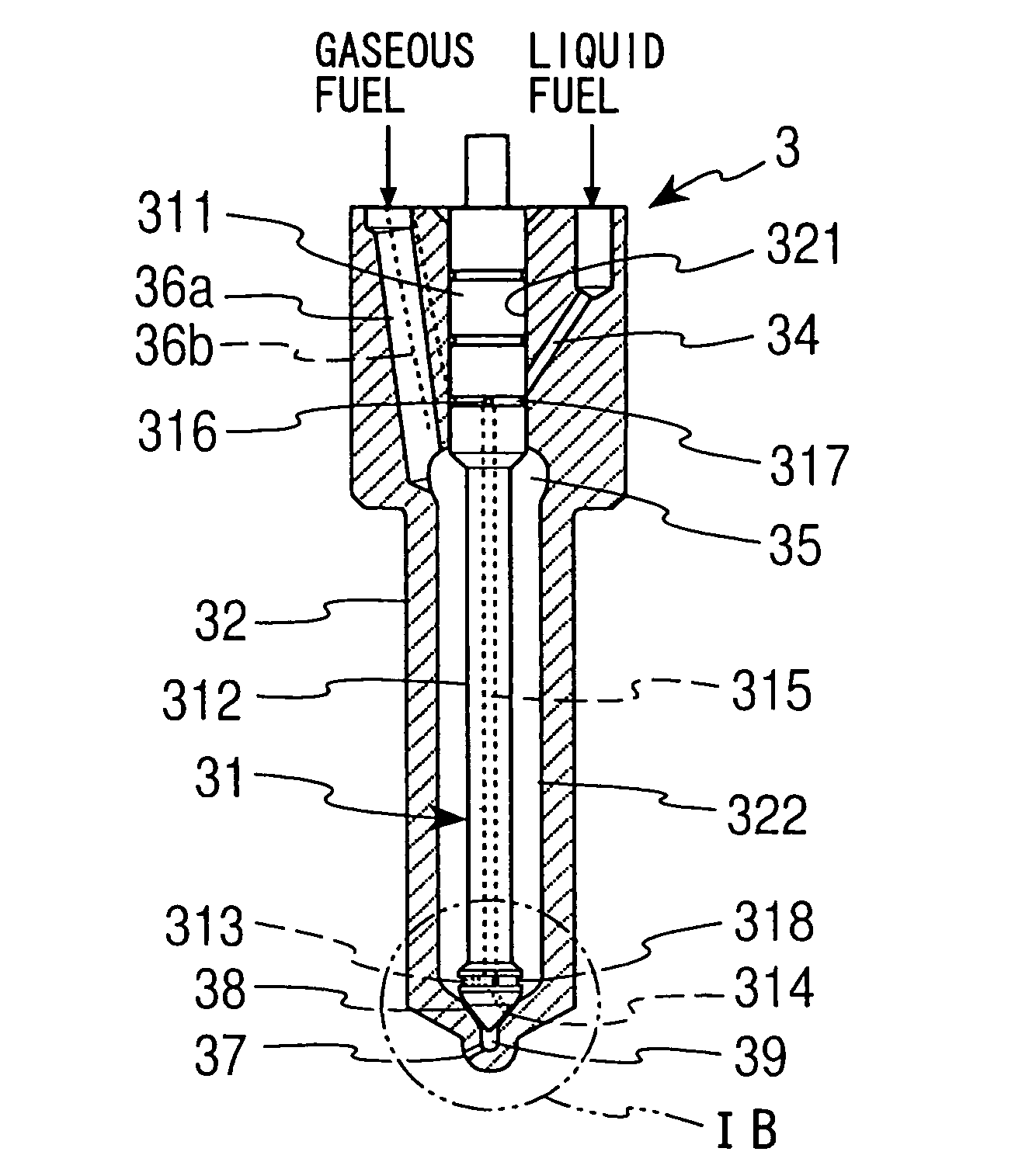
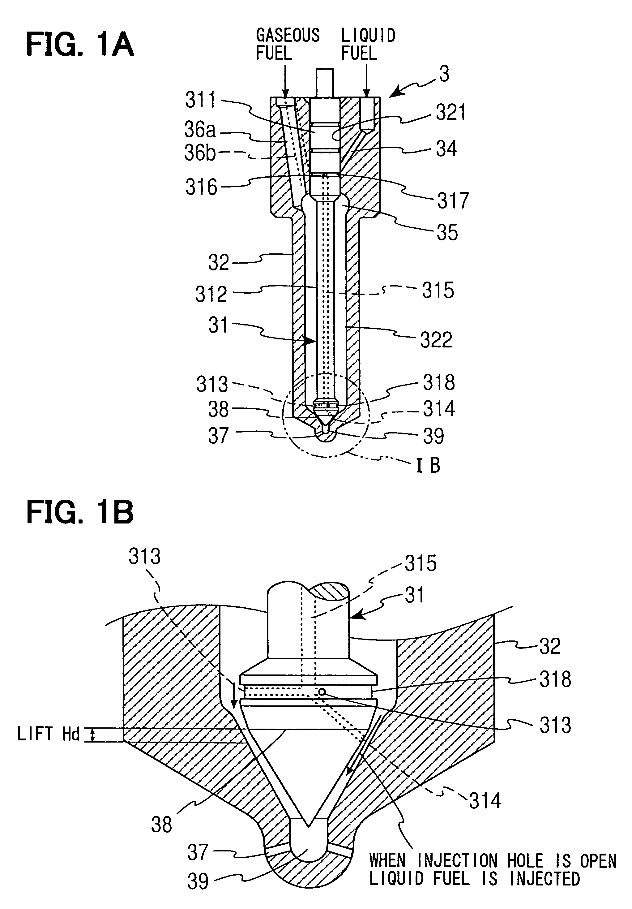
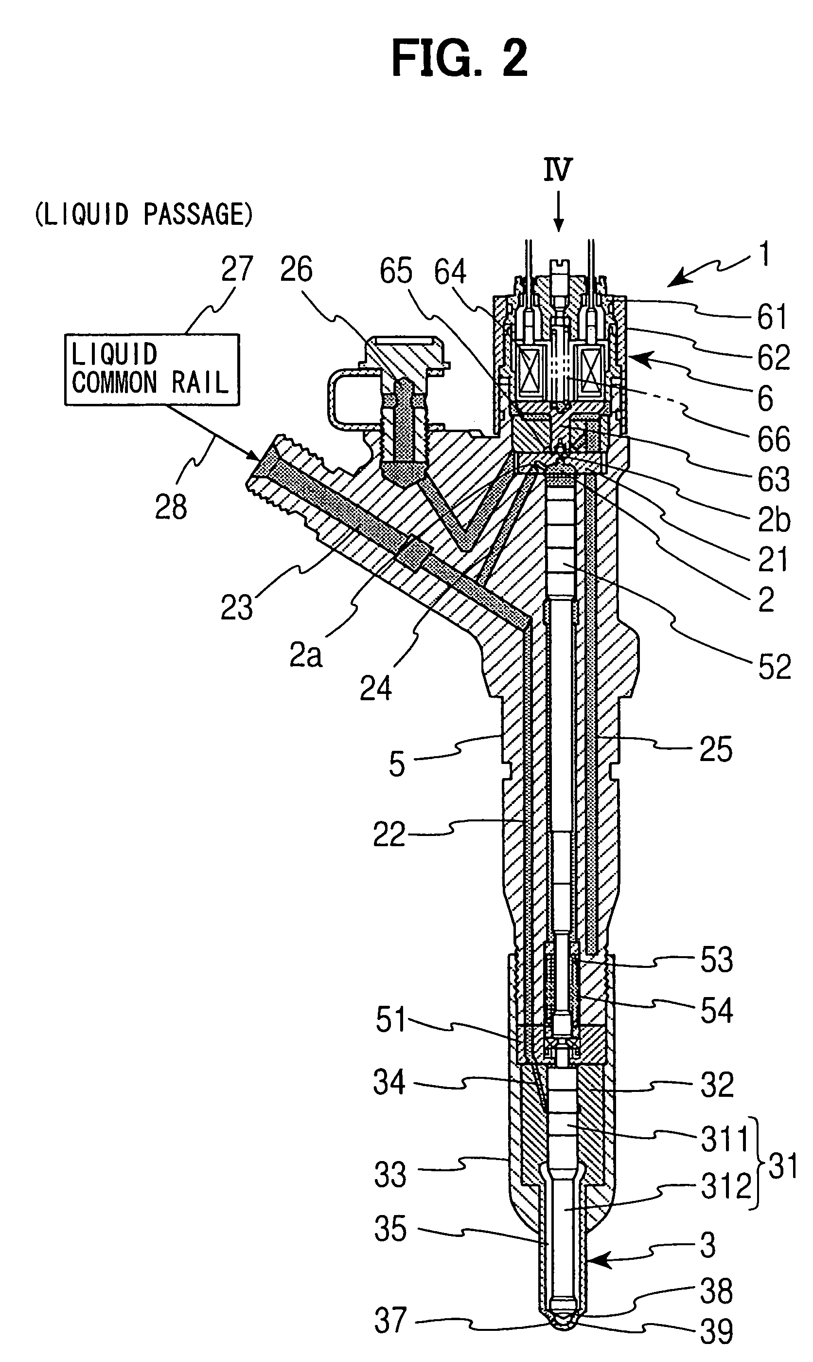
[0022]A first embodiment of a present invention will be described with reference to FIGS. 1A to 4. Injectors 1 according to the first embodiment, directly inject a high-pressure gaseous fuel to cylinders of the multi-cylinder compression ignition engine. Each combustion chamber of the cylinder has the corresponding injector 1.
[0023]FIGS. 2 and 3 are longitudinal sectional views of the injector 1 according to the present embodiment. FIG. 1B is an enlarged view of a nozzle 3, which is a main part of the injector 1 according to the present embodiment. FIG. 2 describes a distribution passage of a working fluid, which is supplied to a control chamber 2 to drive the nozzle 3. FIG. 3 describes a supply passage of a high-pressure gaseous fuel, which is injected from the nozzle 3. A hydrogen fuel may serve as the high-pressure gaseous fuel. A liquid fuel, such as a light oil, serves as the working fuel. FIG. 4 is a plan view of the injector 1, which is a view from a direction indicated by IV...
second embodiment
[0050]A second embodiment will be described with reference to FIGS. 5 and 6. A present invention according to the second embodiment is different from the invention according to the first embodiment in the following points. The second high-pressure liquid passage 34 opens at the annular groove 317 when the needle 31 closes the injection holes 37 (or when the needle 31 is placed in a communication position). The seat lubrication liquid fuel supply hole 313 at the lower end portion of the needle 31 is located at immediately upstream of the seating part 38. The ignition facilitating liquid fuel supply hole 314 at the lower end portion of the needle 31 is located at immediately downstream of the seating part 38. Except for above-mentioned differences, a structure of a present embodiment is similar to that of the first embodiment. Similar components of a gaseous fuel injector 1 of the present embodiment, which are similar to the components of the injector 1 of the first embodiment, will b...
PUM
 Abstract
Description
Claims
Application Information
 - R&D
- Intellectual Property
- Life Sciences
- Materials
- Tech Scout
- Unparalleled Data Quality
- Higher Quality Content
- 60% Fewer Hallucinations
Browse by: Latest US Patents, China's latest patents, Technical Efficacy Thesaurus, Application Domain, Technology Topic, Popular Technical Reports.
© 2025 PatSnap. All rights reserved.Legal|Privacy policy|Modern Slavery Act Transparency Statement|Sitemap|About US| Contact US: help@patsnap.com


