
Laser measurement apparatus using self-mixing effect

a technology of laser measurement and self-mixing, which is applied in the direction of optical radiation measurement, instruments, tubes with screens, etc., can solve the problems of self-mixing effect becoming so small that it cannot be detected in a reliable way, and self-mixing effect may fall below the detection threshold

Active Publication Date: 2008-10-21
TRUMPF PHOTONIC COMPONENTS GMBH
View PDF16 Cites 7 Cited by
  • Summary
  • Abstract
  • Description
  • Claims
  • Application Information

AI Technical Summary

Benefits of technology

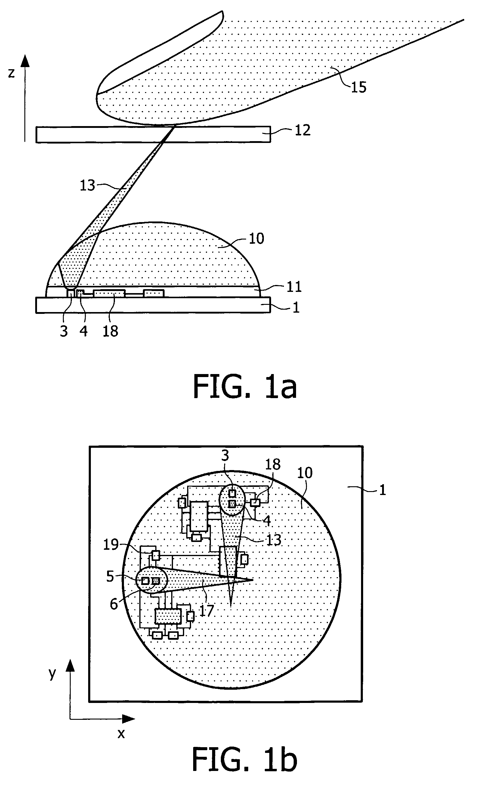
[0006]It is an object of the present invention to provide an input device of the type as described herein before which shows sufficient performance under said circumstances. According to the invention, this input device is characterized in that the converging means are adapted to provide a self-mixing effect that is smaller than a possible maximum but larger than a detection threshold for an extended range of distances between the object and the device window.
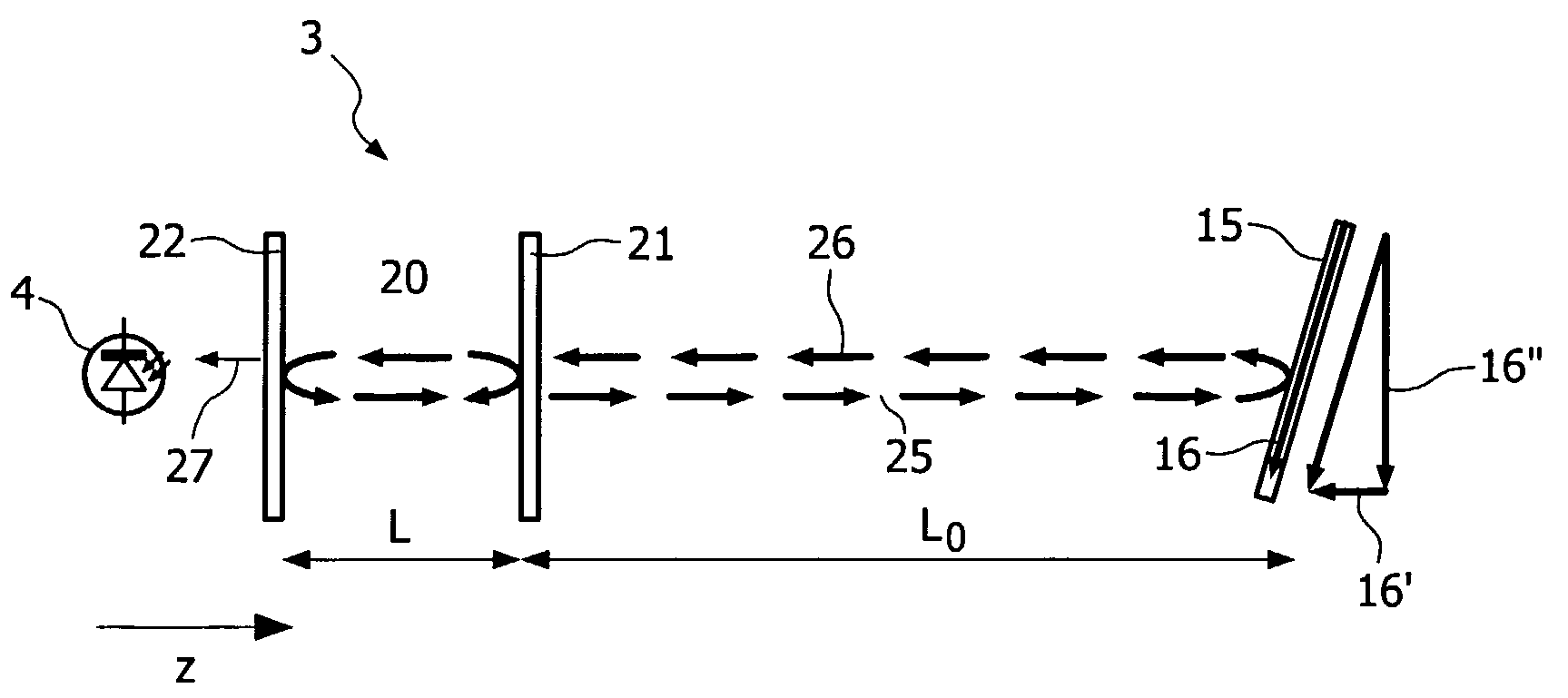
[0009]According to the invention the optical input device is provided with converging means which are adapted to provide for an extended range of distances between the device window and the object a substantially constant spot size on the object and a substantially constant image of this spot in the laser cavity. In this way, the amount of measuring beam radiation re-entering the laser cavity can be kept substantially constant and above a level that corresponds to the detection threshold and the influence of the multi mode behavior of the laser can be reduced. The term substantially constant before spot size and image is understood to mean that the variation of the spot size and of the position of the image respectively is small relative to the mean spot size and the mean position of the image. As an additional advantage, such a small variation allows better performance of the electronic signal detection circuitry.
[0024]This device allows unambiguously discriminating between a scroll action and a click action. Moreover, the number of sensor units may be reduced.

Problems solved by technology

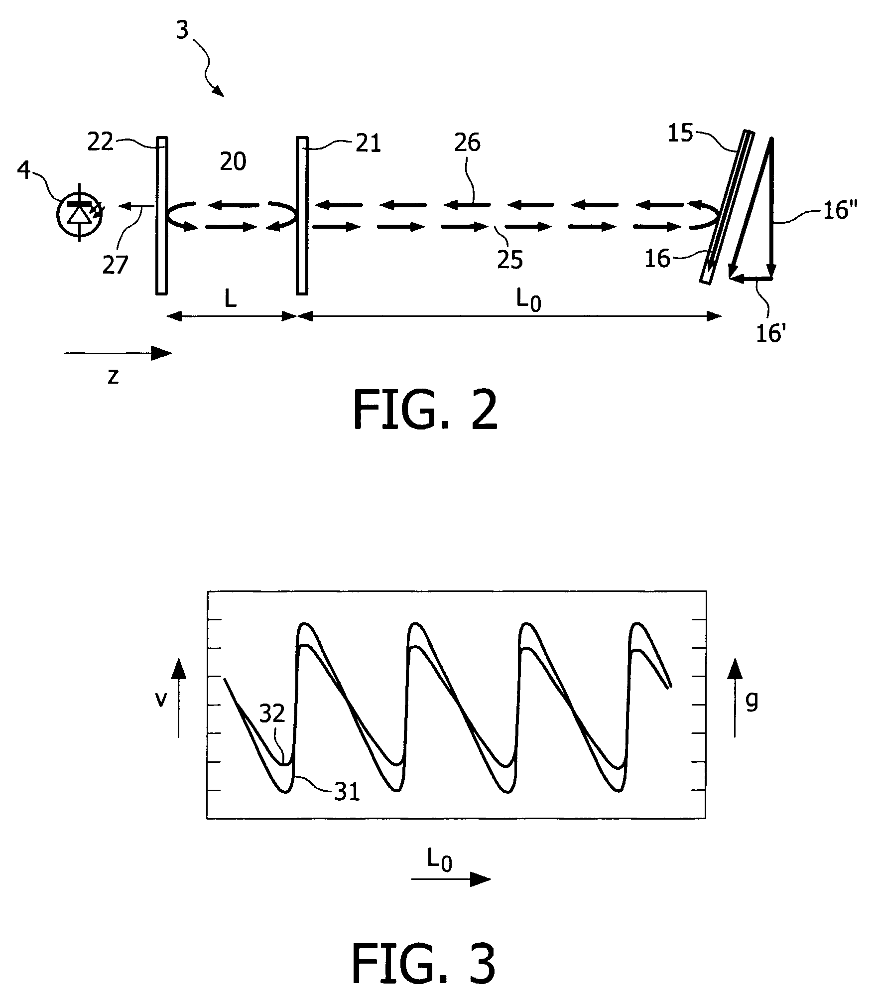
Thus, a relative small shift of the object along the axis of the measuring beam will cause such reduction of the measuring beam radiation re-entering the laser cavity that the self-mixing effect will become so small that it cannot be detected in a reliable way.
For some, unpredictable, distances the self-mixing effect may fall below the detection threshold.

Method used


Image

  • Laser measurement apparatus using self-mixing effect
  • Laser measurement apparatus using self-mixing effect
  • Laser measurement apparatus using self-mixing effect

Examples


first embodiment

[0072]FIG. 4b shows a portion of an input device according to the invention wherein use is made of the aspherical characteristic of a lens 50. Use can be made of the natural asphericity of a lens, because of the large angles at which the beam rays; especially the outer rays are incident on the lens surface. Purely for illustrative purpose the rear surface 54 of the lens 50 is represented as being flattened to a certain degree, i.e. radius of curvature of the refractive surface 54 is larger than the radius of curvature of the front refractive surface 53 to denote asphericity. The boundary rays from object point p1 and passing through lens 50 meet at point p3 in plane PL2, which is closer to the lens 50 than plane PL1. The central rays 43 and 44 passing through lens 50 meet at point p4 in plane PL3, which is farther from the lens than plane PL1 and the intermediate rays passing through lens 50 meet at point p5 between points p3 and p4 and in this embodiment near plane PL1. The lens 50...

second embodiment

[0073]FIG. 4c shows a portion of an input device wherein use is made of asphericity. The asphericity of lens 60 is opposite to that of lens 50 in FIG. 4b. This opposite asphericity can be obtained by shaping the rear refractive surface 64 of lens 60 as a combination of spherical and wedge shape. This lens deflects the rays in a way opposite to the way the rays are deflected by the lens 50. The boundary rays passing through lens 60 meet at point p6 near plane PL3, which is farther from the lens than plane PL1, whilst the central rays meet at point p7 in plane PL2, which is close to the lens than plane PL1. The intermediate rays meet at point p8 in plane PL1. Also for lens 60 holds that the size of the spot formed by it in any plane in the range ΔZ will be substantially constant.

[0074]FIG. 5 shows the effect the lens of FIGS. 4a, 4b and 4c, respectively has on the laser self-mixing effect. The self-mixing effect Sme is plotted along the vertical axis in arbitrary units and the Z-posit...


PUM


Abstract

In an optical input device based on movement of an object (15) and the device relative to each other and which comprising at least one optical sensor unit including a laser (3) having a laser cavity for generating a measuring beam (13), converging means (50) for converging the measuring beam in an action plane and for converging measuring beam radiation reflected by the object in the laser cavity to generate a self-mixing effect in the laser and measuring means for measuring the result of the self-mixing effect, which effect is determined by said movement, the converging means (50) is adapted to provide a self-mixing effect that is smaller than a possible maximum but larger than a detection threshold for an extended range of distances (ΔZ) between the object and the device. This allows obtaining the required self-mixing effect in an extended range of distances between the object and the device.

Description

FIELD OF THE INVENTION[0001]The invention relates to an optical input device based on movement of an object and the device relative to each other, which device comprises a module provided with a transparent window and accommodating at least one optical sensor unit including a laser having a laser cavity for generating a measuring beam, converging means for converging the measuring beam in an action plane and for converging measuring beam radiation reflected by the object in the laser cavity to generate a self-mixing effect in the laser and measuring means for measuring the result of the self-mixing effect, which effect is determined by said movement.[0002]The invention also relates to several types of apparatuses comprising such an optical input device.BACKGROUND OF THE INVENTION[0003]An action plane is understood to mean a plane wherein the measuring beam meets the object and is influenced by the movement of the object and the device relative to each other. The action plane may be ...

Claims


Application Information

Patent Timeline
IPC IPC(8): H01J40/14G06F3/03G06F3/0354G06F3/042
CPCG06F3/0421G06F3/03547G06F3/0354G06F3/042G06F3/03
Inventor LIESS, MARTIN DIETERWEIJERS, ALDEGONDA LUCIA
Owner TRUMPF PHOTONIC COMPONENTS GMBH
Learn More