Motor driving device and automobile using the same

a technology of driving device and motor, which is applied in the direction of motor control for motor oscillation damping, electric pulse generator, electric device, etc., can solve the problems of power device, whether the motor can be held within a thermally allowable level, and the first known example is not suitable for the case, so as to reduce the loss of the first inverter. , the effect of reducing the loss

Inactive Publication Date: 2008-10-21
HITACHI LTD
View PDF7 Cites 72 Cited by
  • Summary
  • Abstract
  • Description
  • Claims
  • Application Information

AI Technical Summary

Benefits of technology

[0012]With those features, in a first mode, the first and second inverters are operated in parallel, whereby the motor currents can supplied in an allocated manner so as to reduce loss. In a second mode, the second inverter is controlled to flow a DC current to the motor windings from the high-voltage battery via the neutral point such that a battery voltage is increased by boosting operation while using the motor windings as a reactor. As a result, the motor can be continuously driven without problems, and the boosting operation and the motor driving can be controlled at the same time.
[0014]With those features, a part of the motor currents for generating a rotating magnetic field is supplied from the second inverter, whereby the loss generated in the first inverter can be reduced.
[0018]With those features, it is possible to make the losses in the first and second inverters as even as possible, to moderate concentration of heat, and to realize an increase in capacity of the motor.
[0020]With those features, electromagnetic noises generated in both the first and second inverters can be canceled each other, thus resulting in small electromagnetic noise.
[0024]With those features, in the first mode, the first and second inverters are operated in parallel, whereby the motor currents can supplied in an allocated manner so as to reduce loss. In the second mode, the second inverter is controlled to flow a DC current to the motor windings from the high-voltage battery via the neutral point such that a battery voltage is increased by boosting operation while using the motor windings as a reactor. As a result, the motor can be continuously driven without problems, and the boosting operation and the motor driving can be controlled at the same time. In addition, a part of the motor currents for generating a rotating magnetic field is supplied from the second inverter, whereby the loss generated in the first inverter can be reduced.

Problems solved by technology

In other words, the first known example is not suitable for the case where the motor is driven in the high speed range while boosting the voltage, as in a hybrid car.
However, since both the AC and DC current components flow trough a power device in the inverter, a loss of the power device is abruptly increased as a DC current used for the boosting operation is increased with respect to the amplitude of an AC current, thus raising a problem in point of whether the motor can be held within a thermally allowable level.
Also, if the waveform of the AC current is distorted by superimposition of the DC current, other problems may occur in that electromagnetic noisy sounds are generated from the motor and electromagnetic noise is caused by the PWM control.
Further, because the boosting operation and the motor driving are controlled at the same time by one inverter, an increase of a maximum current resulting from the superimposition of the DC current may cause breakdown of the power device due to a surge voltage.

Method used


Image

  • Motor driving device and automobile using the same
  • Motor driving device and automobile using the same
  • Motor driving device and automobile using the same

Examples


Embodiment Construction

[0040]The construction and operation of a double-winding motor driving device according to one embodiment of the present invention will be described below with reference to FIGS. 1-13.

[0041]The construction of the double-winding motor driving device according to the one embodiment of the present invention is first described with reference to FIG. 1.

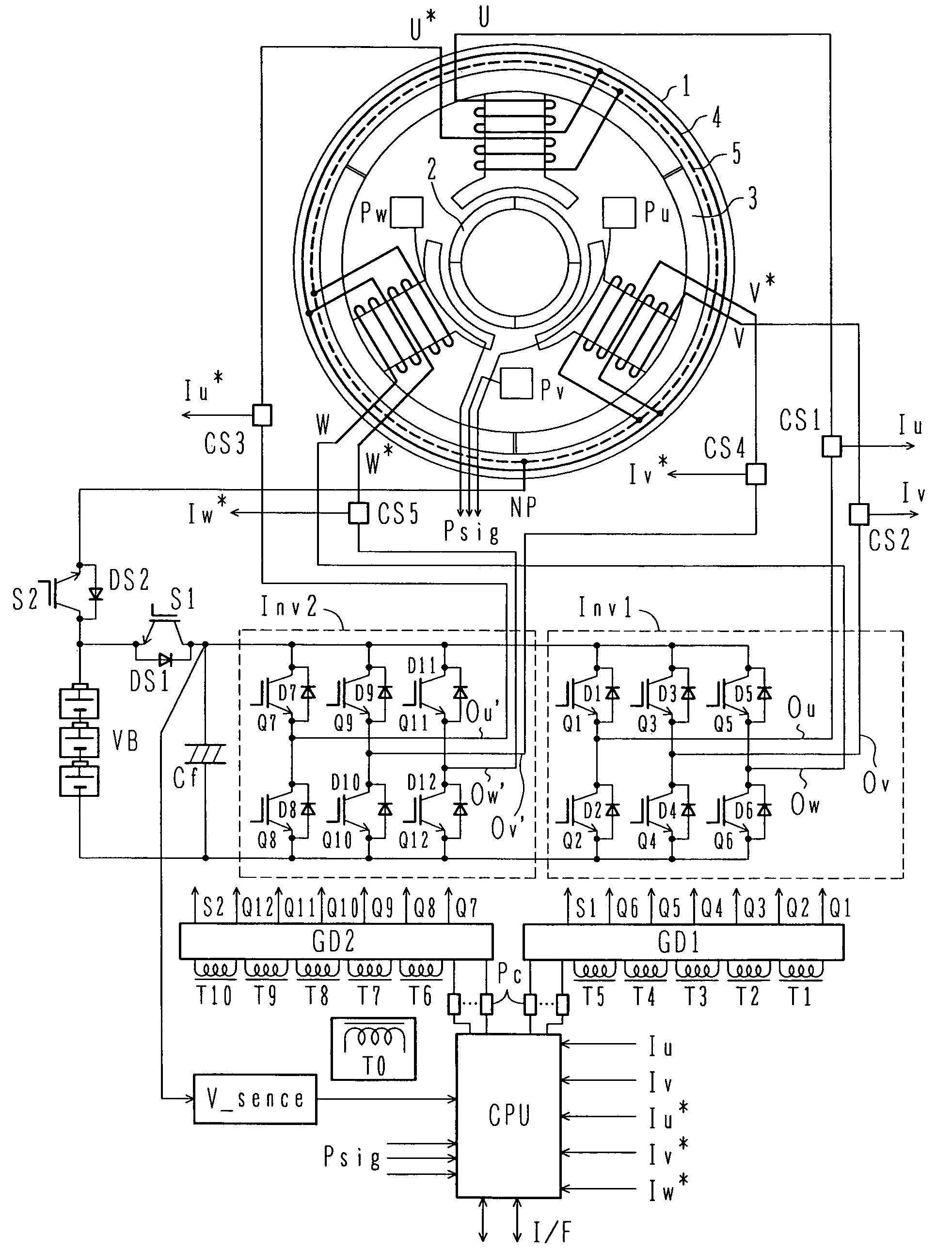
[0042]FIG. 1 is a circuit diagram showing the overall construction of the double-winding motor driving device according to the one embodiment of the present invention.

[0043]A motor 1 is a three-phase permanent-magnet synchronous motor. The motor 1 comprises a rotor 2 including permanent magnets built therein, and a stator 3 made of a magnetic material, e.g., a silicon steel plate. Pairs of double windings U-U*, V-V*, and W-W* are wound respectively over three teeth of the stator 3. While those windings are shown as a concentrated winding structure in the simplified form, the winding structure is not limited to the illustrated one, and oth...


PUM


Abstract

As a boosting-type motor driving device using no reactor, a motor driving device capable of controlling boosting operation and motor driving at the same time is provided, and an automobile using the motor driving device is also provided. The motor driving device is used for driving a motor with a double-winding structure having a first set of three-phase windings and a second set of three-phase winding which are wound over a stator, and includes first and second inverters, which are connected respectively to the first set of three-phase windings and the second set of three-phase windings, thereby controlling the first and second inverters to control a driving force of the motor with the double-winding structure. The first and second inverters have positive and negative terminals which are connected respectively in common to a high-voltage battery. The motor driving device further includes a first switch unit connected between the positive terminals of the first and second inverters connected in common and a positive pole of the high-voltage battery, and a second switch unit connected between a neutral point of the second set of three-phase windings and the positive pole of the high-voltage battery.

Description

BACKGROUND OF THE INVENTION[0001]1. Field of the Invention[0002]The present invention relates to a motor driving device suitably used to assist driving torque of an automobile by using a motor as in the case of a hybrid car, and to an automobile using the motor driving device. More particularly, the present invention relates to a motor driving device suitable for driving a motor with a doubling winding structure, and to an automobile using the motor driving device.[0003]2. Description of the Related Art[0004]Recently, in the industrial field of automobiles, importance has been laid in improving fuel economy and cleaning exhaust gas from the viewpoint of adaptation for environmental issues, and attention has been focused on a hybrid car using a motor to assist torque in a speed range where fuel economy efficiency of an engine is not so high. A motor is superior in torque response to an engine and is expected to not only improve fuel economy, but also to serve as a useful component in...

Claims


Application Information

Patent Timeline
Patent Type & Authority Patents(United States)
IPC IPC(8): H02P6/00H02K7/20B60L50/15B60L50/16H02P21/05H02P21/18H02P21/22H02P21/24H02P23/04H02P25/22H02P27/06H02P27/08
CPCB60L11/123B60L11/14B60L15/025H02P21/04H02P25/18B60L2220/14B60L2260/28Y02T10/6217Y02T10/643Y02T10/7005Y02T10/7077B60L2220/58Y02T10/641B60L50/61B60L50/16H02M7/53875H02M7/493Y02T10/64Y02T10/62Y02T10/70Y02T10/7072H02M1/0048H02M7/48
Inventor MIYAZAKI, HIDEKIKANEKO, SATORU
Owner HITACHI LTD
Why Eureka
Try Eureka