Electrical wiring device switch assembly and combination device with circuit protection component

a technology of circuit protection and electrical wiring devices, which is applied in the direction of circuit-breaking switches, contact-welding prevention/breaking, relays, etc., can solve the problems of heating to ignite nearby combustibles, shock hazards, and fire hazards

Inactive Publication Date: 2008-10-21
PASS SEYMOUR
View PDF13 Cites 20 Cited by
  • Summary
  • Abstract
  • Description
  • Claims
  • Application Information

AI Technical Summary

Problems solved by technology

Ground fault conditions are an unintended current path from the line conductor having faulty or damaged insulation to ground.
The shock hazard occurs when someone contacts ground and the line conductor at the same time.
A fire hazard may occur if the ground fault current results in sufficient heating to ignite nearby combustibles.
Hazardous arc fault conditions (known as series arc faults) may result from a poor electrical connection in the electrical distribution system supplying power to the load.
Hazardous arcing conditions (known as parallel arc faults) may result from a line to line conductor, line to neutral conductor, or line to ground conductor, due to faulty or damaged insulation.
Since the protective device includes both electronic and mechanical components, failure modes may result from normal aging of electronic components, corrosion of mechanical parts, poor connections, mechanical wear, mechanical or overload abuse of the protective device in the field, electrical disturbances such as from lightning, or the like.
One disadvantage of known combination devices is that the user accessible switch toggles in a motion that is parallel to the minor (latitudinal) axis of the device.
The user of the device does not find such rocking motion to be ergonomic.
Another disadvantage is that such rocking motion is not consistent with other wiring devices whose rocking motion is perpendicular to the minor axis of the device.
Another disadvantage of known combination devices is that the user accessible switch portion of the combination device has been limited in number to a single switch.

Method used


Image

  • Electrical wiring device switch assembly and combination device with circuit protection component
  • Electrical wiring device switch assembly and combination device with circuit protection component
  • Electrical wiring device switch assembly and combination device with circuit protection component

Examples


Embodiment Construction

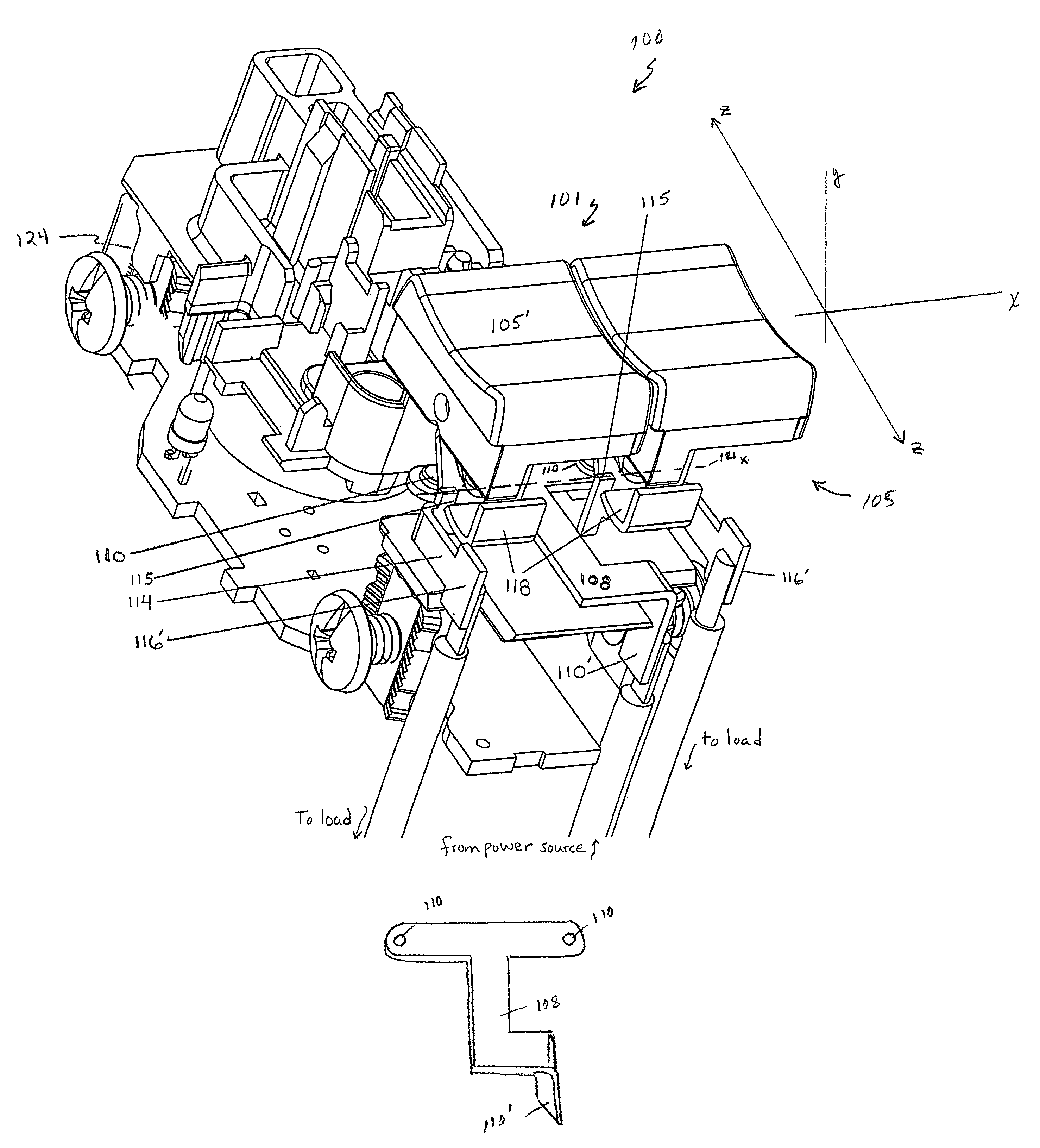
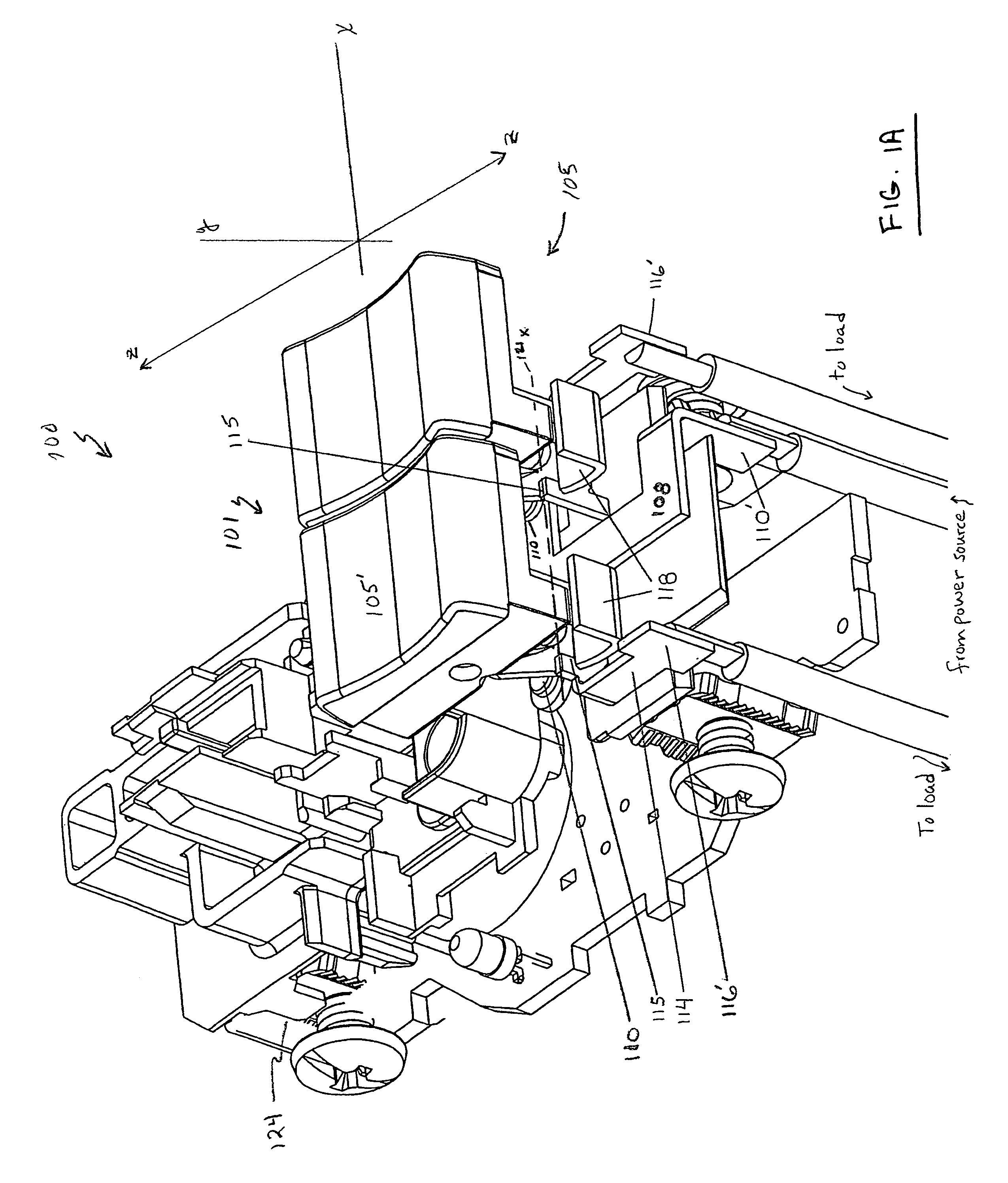
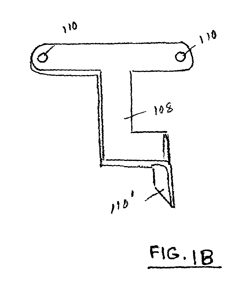
[0044]An embodiment of the invention is directed to an electrical wiring device for use in an electrical distribution system that includes a power source. The device 100, illustrated in part in FIGS. 1A and 2, includes a switch assembly 101 that controls the flow of electricity from the power source, including from a hot load terminal or a hot line terminal, to a load terminal. Although a switch assembly 101 including two switches 105 is depicted in the figures, the principals of operation and the components of each switch apply to a single switch or to two or more switches. Disposed within the bottom portion 104b of device housing 104 as shown in FIG. 3 is a switch frame 107 for holding the switch components, hereinafter referred to collectively as switch 105. The switch 105 includes a user-accessible surface 105′, a pivot assembly 114 having a cradle 115 and a load terminal 116′ that is configured to be user-connectible to a load. The pivot assembly 114 further includes a pivot me...


PUM


Abstract

An electrical wiring device including a plurality of independent switches and a circuit interrupter. In an aspect, two adjacent switches are provided. The user accessible portions of the switches operate in a direction parallel to the major longitudinal axis of the electrical wiring device. A protected receptacle may also be provided. The circuit protection component includes a line terminal connectable to a source of voltage, a load terminal connectable to a load, a circuit interrupter that is configured to connect or disconnect the line terminal from the load terminal, a fault detection circuit that is configured to detect at least one predetermined condition, and a trip mechanism in operable communication with the circuit interrupter to disconnect the line terminal from the load terminal upon detection of the predetermined condition. In an aspect, an electrical wiring device includes a common member having a plurality of fixed contacts and a common terminal configured to be user connectable to a hot line or a hot load source.

Description

RELATED APPLICATION DATA[0001]This application claims priority to U.S. Provisional Application Ser. No. 60 / 553,795 filed on Mar. 16, 2004.FIELD OF THE INVENTION[0002]Embodiments of the invention generally relate to the field of electrical wiring devices and, more particularly, to an electrical wiring device including a switch assembly and to an electrical wiring device including one or more of the switch assemblies in combination with a circuit protection component.BACKGROUND OF THE INVENTION[0003]The switch component of an electrical wiring device typically includes a user accessible switch arm, rocker paddle, push button, touch pad, etc. (“switching surface”), a lever arm or suitable linkage attached to the backside of the switching surface, and a line side contact that can be connected / disconnected from a load side contact via operation of the switching surface by the user. A common single switch device for activating a remote receptacle or light, for example, typically presents ...

Claims


Application Information

Patent Timeline
Patent Type & Authority Patents(United States)
IPC IPC(8): H01H73/00H01H73/12H01H75/00
CPCH01H23/168H01H1/50H01H3/001H01H23/166H01H23/205
Inventor RADOSAVLJEVIC, DEJANWEEKS, RICHARD
Owner PASS SEYMOUR
Why Eureka
Try Eureka