Magnetoresistive head using longitudinal biasing method with 90-degree magnetic interlayer coupling and manufacturing method thereof

a technology of longitudinal biasing and magnetic interlayer coupling, applied in the direction of magnetic recording heads, magnetic recording instruments, etc., can solve the problems of reducing output, difficult control of the magnetization direction of the layer applying a longitudinal biasing field to the pinned layer and the free layer, and reducing the effect of the demagnetizing field in the free layer at the track edges

Inactive Publication Date: 2008-10-21
HITACHI GLOBAL STORAGE TECH NETHERLANDS BV
View PDF11 Cites 11 Cited by
  • Summary
  • Abstract
  • Description
  • Claims
  • Application Information

AI Technical Summary

Benefits of technology

[0011]With improving the areal recording density of a magnetic recording system in the future, the track width becomes narrower. Because of this, according to the reasons described above, it is expected that realizing high read sensitivity compatible with excellent linear response properties with low noise will become difficult. In the currently proposed in-stack biasing structure as a means of applying an alternate longitudinal biasing field in a hard bias structure, there is concern that control of the magnetization direction of the layer applying a longitudinal biasing field to the pinned layer and the free layer is difficult, and making a single magnetic domain is prevented by the influence of a demagnetizing field because of creation of magnetic poles at the track edges of the free layer.
[0012]It is a feature of the present invention to provide a mechanism for easily controlling the magnetization direction of the ferromagnetic layer applying a longitudinal biasing field to the pinned layer and the free layer and for controlling the influence of the demagnetizing field at the track edges of the free layer in a magnetoresistive head having an in-stack biasing structure.
[0015]It is preferable that the second ferromagnetic layer has at least two ferromagnetic layers, and the aforementioned ferromagnetic layers have so-called “synthetic ferromagnetic” structures in which these layers are laminated through an antiferromagnetic coupling layer. The magnetization of the second ferromagnetic layer is fixed in the direction along the sensor height, so that an in-plane biasing field is applied to the free layer proportional to the magnetic moment. Therefore, it is preferable that the second ferromagnetic layer has a synthetic ferromagnetic structure, and the effective magnetic moment of the second ferromagnetic layer is reduced.
[0020]Therefore, according to the present invention, the magnetizations of the pinned layer and the second ferromagnetic layer can be easily fixed nearly in the direction along the sensor height, and, at the same time, the magnetization of the ferromagnetic layer applying the longitudinal biasing field to the free layer can be automatically directed nearly to the track width direction. Moreover, because magnetic flux returns between the free layer and the first ferromagnetic layer at the track edges, the influence of the demagnetizing field in the free layer at the track edges can be controlled.
[0021]According to the present invention, the magnetization direction of the ferromagnetic layer applying a longitudinal biasing field to the pinned layer and the free layer can be easily controlled and, moreover, the influence of the demagnetizing field in the free layer at the track edges can be reduced; therefore, a magnetoresistive head and a manufacturing process thereof can be provided, in which excellent read sensitivity and reproducing properties with low noise and high reliability can be achieved, even when the track width becomes narrower.

Problems solved by technology

Because of this, according to the reasons described above, it is expected that realizing high read sensitivity compatible with excellent linear response properties with low noise will become difficult.
In the currently proposed in-stack biasing structure as a means of applying an alternate longitudinal biasing field in a hard bias structure, there is concern that control of the magnetization direction of the layer applying a longitudinal biasing field to the pinned layer and the free layer is difficult, and making a single magnetic domain is prevented by the influence of a demagnetizing field because of creation of magnetic poles at the track edges of the free layer.
However, when the antiferromagnetic interlayer coupling between the free layer and first ferromagnetic layer is made too strong, a problem arises that the output is decreased because the magnetization of the free layer becomes difficult to rotate by the signal field of the medium.

Method used


Image

  • Magnetoresistive head using longitudinal biasing method with 90-degree magnetic interlayer coupling and manufacturing method thereof
  • Magnetoresistive head using longitudinal biasing method with 90-degree magnetic interlayer coupling and manufacturing method thereof
  • Magnetoresistive head using longitudinal biasing method with 90-degree magnetic interlayer coupling and manufacturing method thereof

Examples


embodiment 1

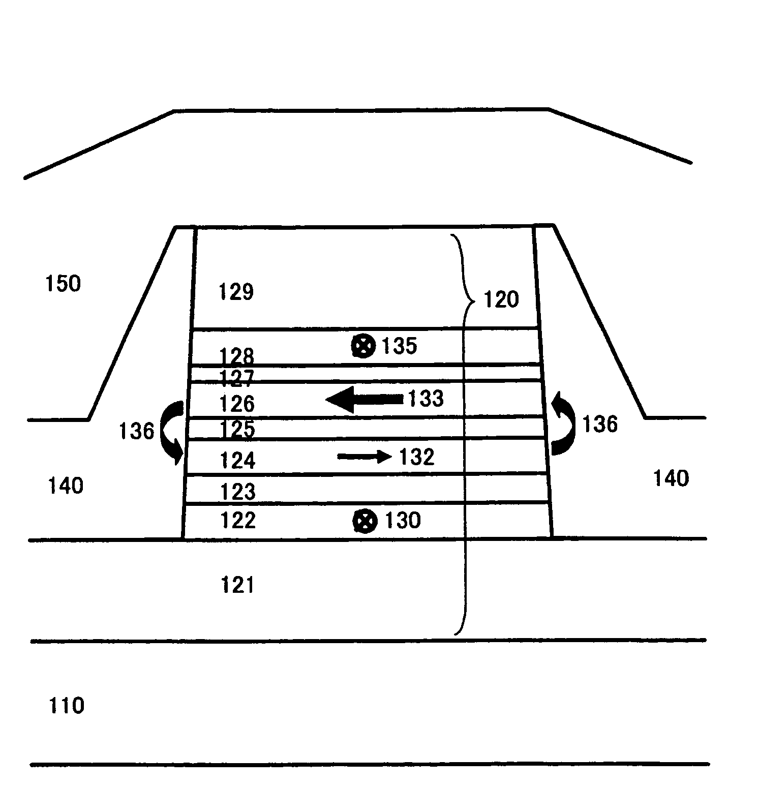
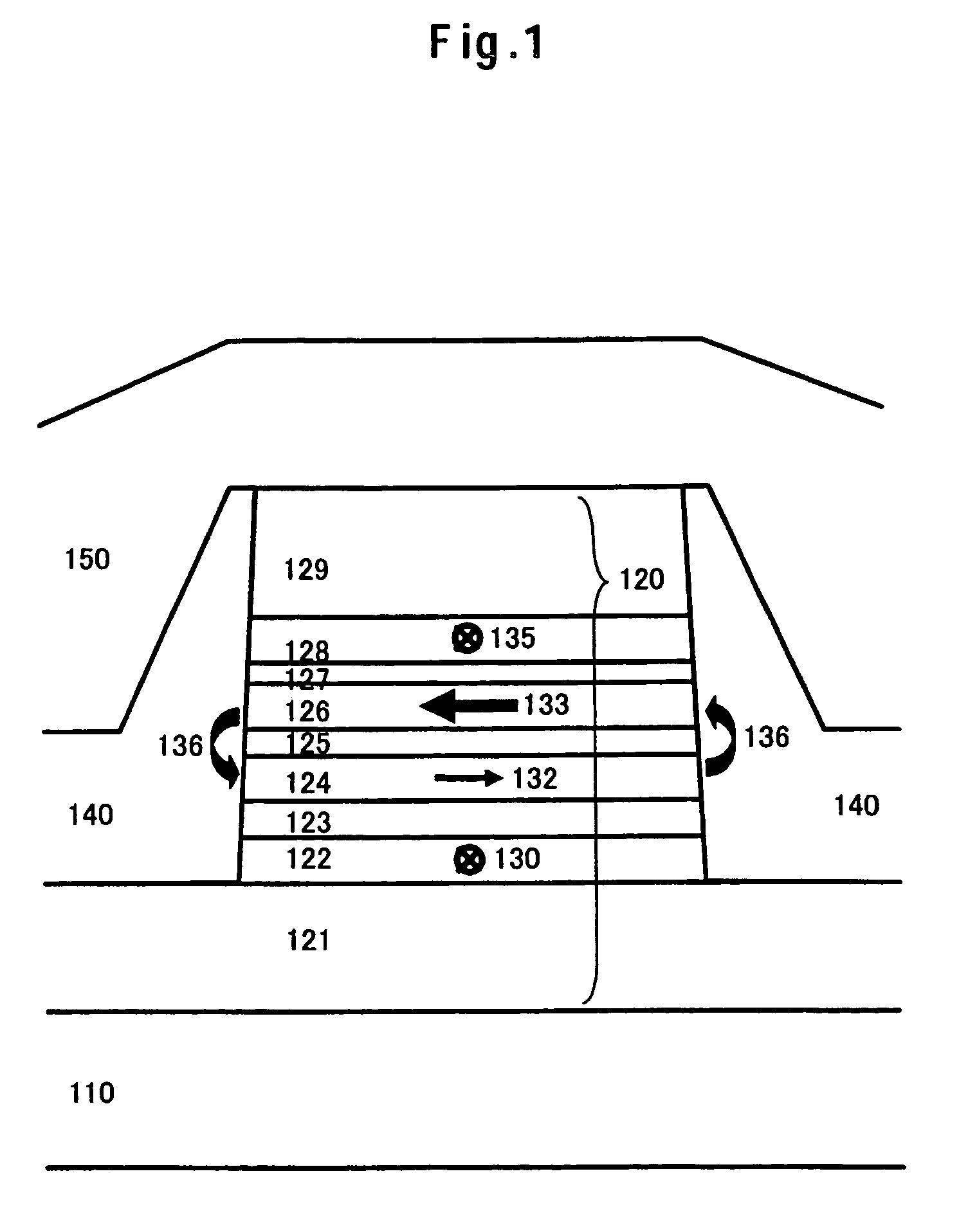
[0038]FIG. 1 is a schematic diagram illustrating an example of a magnetoresistive head of the embodiment 1 of the present invention as seen from the air bearing surface. The structure together with an outline of the fabricating procedure of a magnetoresistive head will be described below.

[0039]A magnetoresistive film 120 is deposited on the substrate (not shown in the figure) after forming a lower shield 110, and the track width direction is patterned into a desired shape by using photolithography, ion milling, or reactive ion etching. Next, an insulator layer 140 is formed at both ends of the magnetoresistive film 120 using a lift-off method. Similarly, in the direction along the sensor height, the magnetoresistive film 120 is patterned into a desired shape by using photolithography, ion milling, or reactive ion etching, and the insulator layer is formed using a lift-off method. The order of patterning the magnetoresistive film 120 may also be exchanged between the track width dire...

embodiment 2

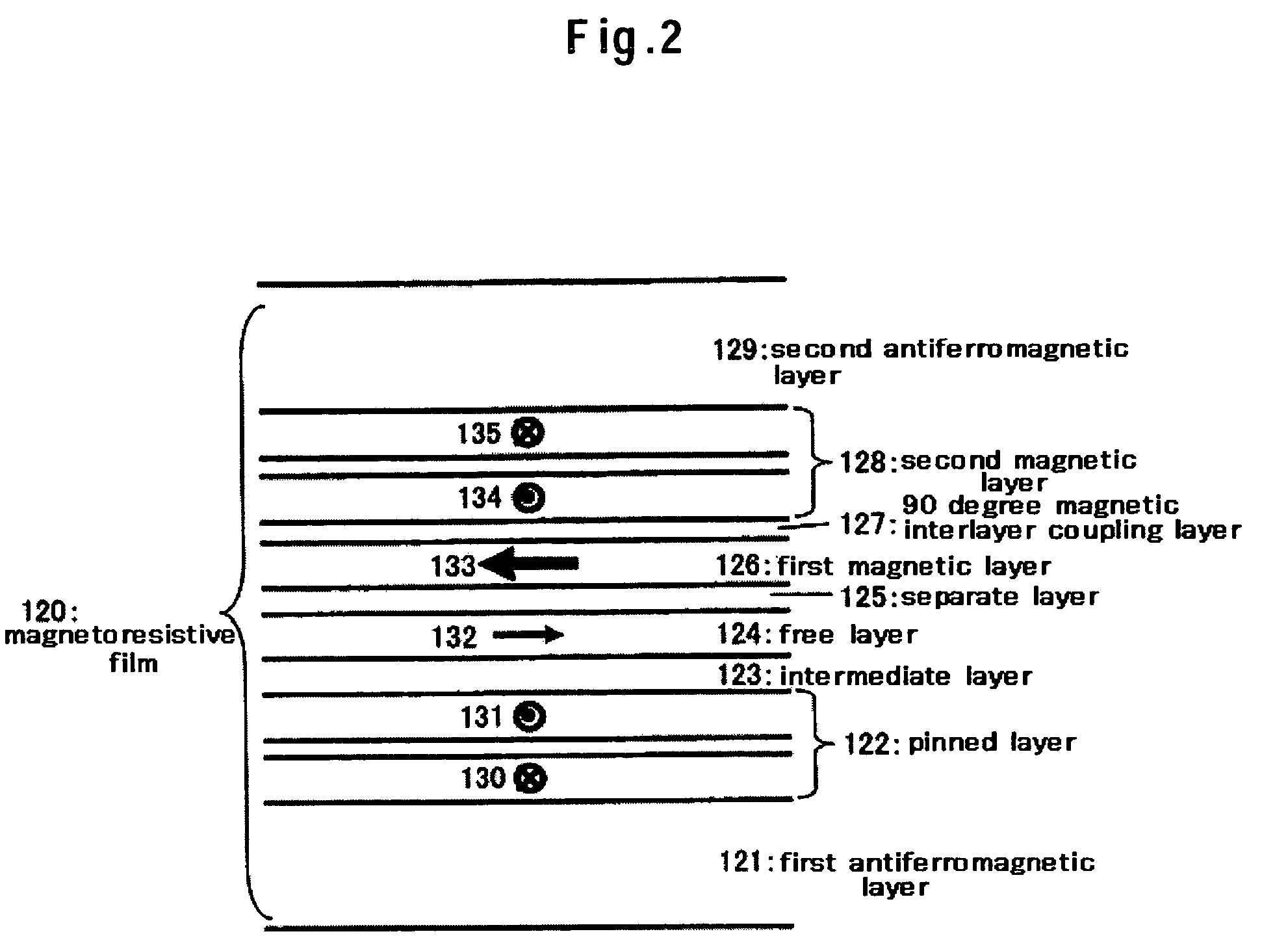
[0064]FIG. 9 is a schematic diagram illustrating an example of a magnetoresistive film 220 of the embodiment 2 of the present invention as seen from the air bearing surface. It is a magnetoresistive head in which the magnetoresistive film 120 of the embodiment 1 of the present invention is only substituted by the magnetoresistive film 220, so that the detailed head configuration is omitted. In this embodiment, it has a structure in which the second antiferromagnetic layer 129 is removed from a part of the system of the embodiment 1 for applying a longitudinal biasing field: separate layer 125 / first ferromagnetic layer 126 / 90-degree magnetic interlayer coupling layer 127 / second ferromagnetic layer 128 / second antiferromagnetic layer 129. That is, the second ferromagnetic layer 128 has a so-called “self-pinned” structure consisting of ferromagnetic layer 1 / antiferromagnetic coupling layer / ferromagnetic layer 2, thereby fixing the magnetization direction of the second ferromagnetic laye...

embodiment 3

[0069]FIG. 10 is a schematic diagram illustrating an example of a magnetoresistive film 320 of the embodiment 3 of the present invention as seen from the air bearing surface. It is a magnetoresistive head in which the magnetoresistive film 120 of the first embodiment of the present invention is only substituted by the magnetoresistive film 320, so that the detailed head configuration is omitted. This embodiment has a structure in which the second antiferromagnetic layer 129 is removed from a part of the system of applying a longitudinal biasing field of the first embodiment: separate layer 125 / first ferromagnetic layer 126 / 90-degree magnetic interlayer coupling layer 127 / second ferromagnetic layer 128 / second antiferromagnetic layer 129, and in which the second ferromagnetic layer 128 consists of a hard magnetic material and the magnetic direction of the second ferromagnetic layer 128 is fixed in the direction along the sensor height. A material selected from Co—Pt and one in which C...


PUM

PropertyMeasurementUnit
thicknessaaaaaaaaaa
thicknessaaaaaaaaaa
temperatureaaaaaaaaaa

Abstract

A magnetoresistive head and a fabricating method thereof accomplishing high read sensitivity and excellent linear response with low noise even if track width narrowing makes progress are provided. In one embodiment, using a magnetoresistive film having a laminated body of a pinned layer / an intermediate layer / a free layer / a separate layer / a first ferromagnetic layer / a 90-degree magnetic interlayer coupling layer / a second ferromagnetic layer, and the magnetizations of both the pinned layer and the second ferromagnetic layer are fixed nearly in the direction along the sensor height. On the other hand, the magnetizations of the first ferromagnetic layer and the second ferromagnetic layer have an interlayer interaction being directed in nearly orthogonal directions to each other through the 90-degree magnetic interlayer coupling layer, and the first ferromagnetic layer has a magnetization directed nearly in the direction along the track width in zero external magnetic field. According to this, the first ferromagnetic layer applies a longitudinal biasing field to the free layer nearly in the direction along the track width.

Description

CROSS-REFERENCES TO RELATED APPLICATIONS[0001]This application claims priority from Japanese Patent Application No. JP2004-330636, filed Nov. 15, 2004, the entire disclosure of which is incorporation herein by reference.BACKGROUND OF THE INVENTION[0002]The present invention relates to a magnetoresistive head mounted in a magnetic recording system. Particularly, it relates to a magnetoresistive head and a manufacturing method thereof by which information recorded in a magnetic medium is reproduced.[0003]At the present time, a GMR (Giant Magneto-Resistive) head using a spin-valve, which has a basic structure consisting of a ferromagnetic layer / nonmagnetic conductive layer / ferromagnetic layer / antiferromagnetic layer disclosed in JP-A No. 358310 / 1992, is generally adopted for a magnetoresistive head mounted in a magnetic recording system as a read sensor. In a spin-valve, a ferromagnetic layer in which the magnetization direction is fixed in one direction by a magnetic exchange coupling...

Claims


Application Information

Patent Timeline
Patent Type & Authority Patents(United States)
IPC IPC(8): G11B5/39
CPCG11B5/39
Inventor HOSHINO, KATSUMIHOSHIYA, HIROYUKIKATADA, HIROYUKIMEGURO, KENICHI
Owner HITACHI GLOBAL STORAGE TECH NETHERLANDS BV
Why Eureka
Try Eureka