Bearingless brushless direct current motor and control method thereof

A technology of brush DC motor and control method, which is applied in the direction of motor generator control, electronic commutation motor control, current controller, etc., and can solve the problem of low utilization rate of permanent magnet materials, small suspension force, bearingless brushless DC motor control Complicated problems, to achieve the effect of saving permanent magnet materials, increasing levitation force, and increasing air gap magnetic density

Active Publication Date: 2012-03-07
ZHENJIANG YUANDONG ELECTRIC MOTOR
View PDF3 Cites 10 Cited by
  • Summary
  • Abstract
  • Description
  • Claims
  • Application Information

AI Technical Summary

Problems solved by technology

[0003] The present invention aims to solve the problems of the existing bearingless brushless DC motors such as complex control, low utilization rate of permanent magnet materials, and small suspension force, and proposes a bearing-less brushless motor with simple control, high utilization rate of permanent magnet materials, and large suspension force. DC motor; Another object of the present invention is to propose a control method of a bearingless brushless DC motor, which can improve the performance of the bearingless brushless DC motor

Method used


Image

  • Bearingless brushless direct current motor and control method thereof
  • Bearingless brushless direct current motor and control method thereof
  • Bearingless brushless direct current motor and control method thereof

Examples


Embodiment Construction

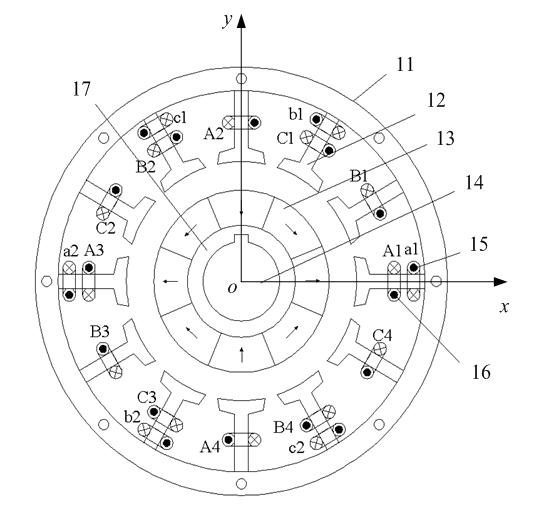
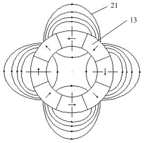
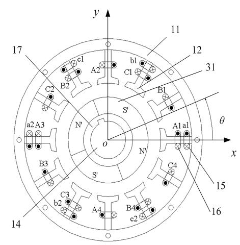
[0014] see Figure 1-3 , The motor is composed of a stator yoke 11, a stator tooth 12, a permanent magnet 13, a rotating shaft 14, a suspension force winding 15, a torque winding 16 and a rotor core 17. The stator yoke 11 is cylindrical, and the stator yoke 11 is covered with a rotating shaft 14, and the rotating shaft 14 is fixed outside the rotor core 17, and the permanent magnets 13 are evenly distributed on the surface of the rotor core 17 in a Halbach array (radial and tangential mixed arrays) . And the stator yoke 11 , the rotating shaft 14 and the rotor core 17 are coaxial. There are 12 stator teeth 12 evenly fixed on the inner circumferential surface of the stator yoke 11 , and 15 sets of suspension force windings and torque windings 16 are all wound on the stator teeth 12 .

[0015] The torque winding 16 is composed of A, B, and C three-phase torque windings, using short-distance windings, and each phase torque winding is composed of four coils, 12 coils in total. ...


PUM


Abstract

The invention discloses a bearingless brushless direct current motor and a control method thereof. The motor is characterized in that: a permanent magnet is uniformly distributed on a surface of a rotor iron core with a Halbach array; both a torque winding and a suspension force winding employ a short pitch winding structure and are wound round a stator tooth together; coils of each two suspension force windings are separated by a stator tooth; through a difference between a given rotating speed and an actual rotating speed and through a PI regulator, a current given value of the torque winding is outputted to control torque winding input current, and rotating speed closed loop control is realized; through a difference between a given rotor radial displacement and a detected actual displacement and through the PI regulator, a suspension force given value is outputted to control suspension force winding input current, and rotor radial displacement closed loop control is realized. By employing the method in the invention, effective control of bearingless brushless direct current motor torque and suspension force are realized, permanent magnetism material is saved, and a motor weight is reduced.

Description

technical field [0001] The invention relates to a bearingless brushless DC motor, which is a three-phase bearingless brushless DC motor with short-distance windings and Halbach array (radial and tangential mixed arrangement array) permanent magnet rotor structure, which is applied to artificial heart blood Special fields such as pumps, left ventricular assist devices, surgical cutting chainsaws, etc. Background technique [0002] The bearingless brushless DC motor is a new type of motor that integrates the magnetic bearing and the brushless DC motor on the basis of the traditional brushless DC motor structure. It places the suspension force winding directly in the stator slot, so that the suspension force winding and the torque winding share the stator core. At present, the commonly used bearingless brushless DC motors are full-pitch or long-pitch windings. The suspension force winding and torque winding with common teeth are energized at the same time. The magnetic field g...

Claims


Application Information

Patent Timeline
Patent Type & Authority Applications(China)
IPC IPC(8): H02K29/00H02K1/27H02K1/14H02K3/28H02K3/46H02P21/14H02P6/28
Inventor 朱熀秋陈雷刚许波潘伟孙晓东
Owner ZHENJIANG YUANDONG ELECTRIC MOTOR
Why Eureka
Try Eureka