Method for producing iron-based oxide magnetic particle powder

a technology of magnetic particle powder and iron-based oxide, which is applied in the direction of magnetic materials for record carriers, instruments, cobalt-containing materials, etc., can solve problems such as environmental stability degradation, and achieve the effect of enhancing the recording density of the magnetic recording medium and the magnetic recording characteristics

Active Publication Date: 2018-07-26
DOWA ELECTRONICS MATERIALS CO LTD
View PDF2 Cites 10 Cited by
  • Summary
  • Abstract
  • Description
  • Claims
  • Application Information

AI Technical Summary

Benefits of technology

[0024]By using the production method of the invention, an iron-based oxide magnetic particle powder can be provided that has a narrow particle size distribution and particularly a small content of the fine particles that do not contribute to the enhancement of the magnetic recording characteristics, which result in a narrow coercive force distribution, and is suitable for the enhancement of the recording density of the magnetic recording medium.

Problems solved by technology

However, the refinement of the magnetic particles generally tends to cause deterioration of the environmental stability and the thermal stability thereof, which raises concerns about the deterioration of the magnetic characteristics of the magnetic particles under the use or storage environment, and accordingly, various partially substituted materials of ε-Fe2O3 represented by the general formula ε-AxByFe2-x-yO3 or ε-AxByCzFe2-x-y-zO3 (wherein A represents a divalent metal element, such as Co, Ni, Mn, and Zn; B represents a tetravalent metal atom, such as Ti; and C represents a trivalent metal element, such as Ga and Al) that have a reduced particle size and a variable coercive force and are excellent in environmental stability and thermal stability, by substituting a part of Fe sites of ε-Fe2O3 by another metal that is excellent in heat resistance have been developed (PTL 3).

Method used


Image

  • Method for producing iron-based oxide magnetic particle powder
  • Method for producing iron-based oxide magnetic particle powder
  • Method for producing iron-based oxide magnetic particle powder

Examples


example 1

[0104]To 3,214.78 g of pure water in a 5 L reaction vessel, 291.32 g of ferric(III) nitrate nonahydrate having a purity of 99.4%, 80.18 g of a Ga(III) nitrate solution having a Ga concentration of 10.1%, 6.58 g of cobalt(II) nitrate hexahydrate having a purity of 97%, and 7.14 g of titanium(IV) sulfate having a Ti concentration of 14.7% were dissolved by mechanically stirring with a stirring blade in the air atmosphere under condition of 40° C. The charged solution had a molar ratio of metal ions of Fe / Ga / Co / Ti=1.635 / 0.265 / 0.050 / 0.050. The numeral in parentheses following the compound name shows the valence of the metal element.

[0105]In the air atmosphere at 40° C., 166.29 g of an ammonia solution of 21.2% was added at once under mechanically stirring with a stirring blade to make pH after neutralization of 1.0 or more and 3.0 or less, followed by continuously stirring for 2 hours. The turbid brown solution in the initial stage of addition was changed to a transparent brown reaction...

examples 2 and 3

[0117]Iron-based oxide magnetic particle powder was obtained in the same manner as in Example 1 except that D / (Fe+M) was 0.2 (Example 2) or 0.3 (Example 3), and the baking temperature of the oxide was 1,055° C. in Example 3.

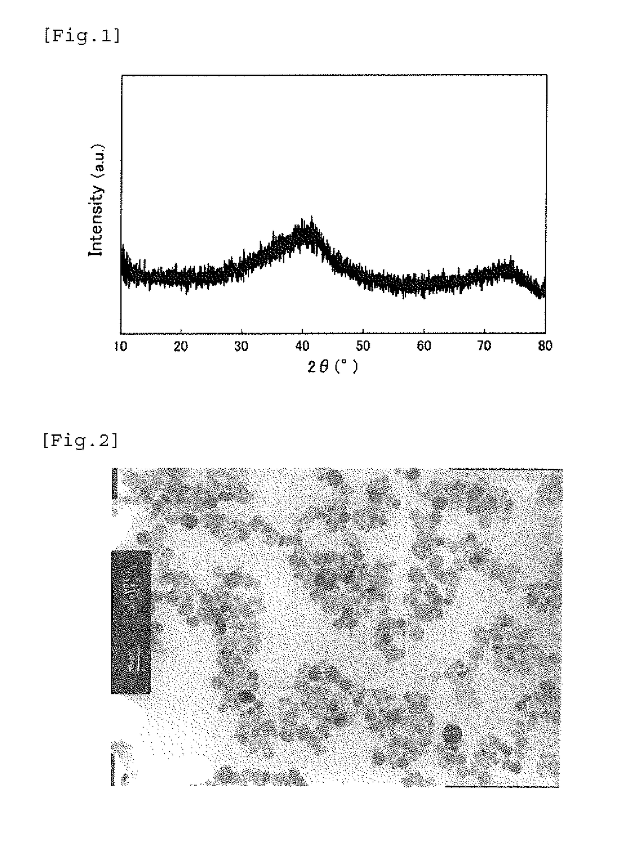
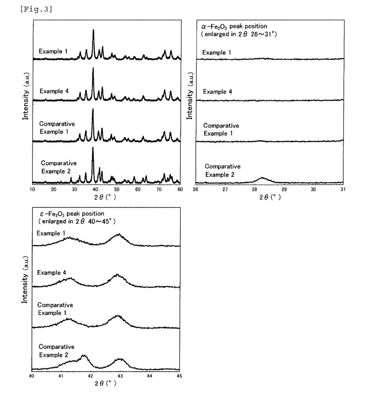
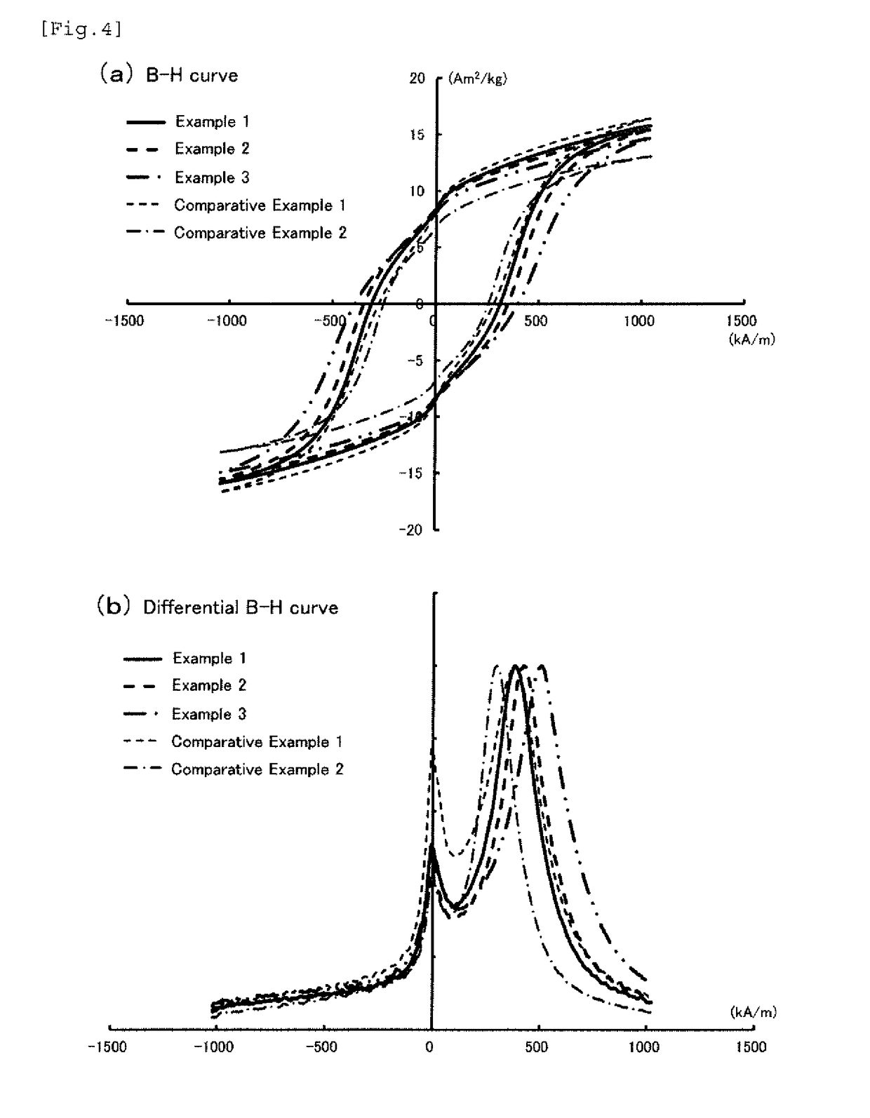
[0118]FIG. 4 shows (a) the B-H curves and (b) the differential B-H curves of the iron-based oxide magnetic particle powder obtained in this example, and the measurement results including the average particle diameter and the like of the iron-based oxide magnetic particle powder obtained in these examples are shown in Table 1. FIG. 7 shows the X-ray diffraction pattern of the iron-based oxide magnetic particle powder obtained in Example 2 and the enlarged views thereof around the diffraction angle of 28° and the diffraction angle of 42° , which show the substantially same crystal structure as ε-Fe2O3.

[0119]The iron-based oxide magnetic particle powder obtained in Example 2 had an average particle diameter of 17.0 nm and a coefficient of variation (CV value) of 41....

examples 4 to 6

[0121]Iron-based oxide magnetic particle powder was obtained in the same manner as in Example 1 except that the reaction temperature from the first neutralizing step to the second neutralizing step was 20° C., and D / (Fe+M) was 0.15 (Example 4, the same condition as in Example 1), 0.2 (Example 5, the same condition as in Example 2), or 0.3 (Example 6, the same condition as in Example 3), and the baking temperature of the oxide was 1,055° C. in Example 6. The measurement results including the average particle diameter and the like of the iron-based oxide magnetic particle powder obtained in these examples are shown in Table 1. In the case where the reaction temperature was lowered to 20° C., there was no significant improvement effect observed for SFD and IL / IH, but the value of αs / εs became a value of 0.10 or less, i.e., 0.04 (Example 4), 0.05 (Example 5), or 0.05 (Example 6).


PUM

PropertyMeasurementUnit
particle diameteraaaaaaaaaa
pHaaaaaaaaaa

Abstract

To provide iron-based oxide magnetic particle powder that has a narrow particle size distribution and a small content of fine particles that do not contribute to the magnetic recording characteristics, which result in a narrow coercive force distribution, and is suitable for the enhancement of the recording density of the magnetic recording medium, and a method for producing the same. An alkali is added to an aqueous solution containing a trivalent iron ion and an ion of the metal substituting a part of Fe sites to neutralize the aqueous solution to pH of 1.0 or more and 3.0 or less; a hydroxycarboxylic acid D is added in an amount providing a molar ratio D / Fe with respect to the amount of the trivalent iron ion or a molar ratio (D / (Fe+M)) with respect to the total amount of the trivalent iron ion and the ion of the metal M in the case where the substituting metal ion is contained of 0.125 or more and 1.0 or less; an alkali is further added to neutralize to pH of 7.0 or more and 10.0 or less; and then the iron oxyhydroxide containing the substituting metal element is coated with a silicon oxide and heated, so as to provide ε-type iron-based oxide magnetic particle powder containing the substituting metal element.

Description

TECHNICAL FIELD[0001]The present invention relates to a method for producing an iron-based oxide magnetic particle powder that is suitable for a high density magnetic recording medium, a radio wave absorber, and the like, particularly to the particle powder that has an average particle diameter of particles in nanometer order.BACKGROUND ART[0002]While ε-Fe2O3 is an extremely rare phase among iron oxides, particles thereof having a nanometer order size show a great coercive force (Hc) of approximately 20 kOe (1.59×10⁶ A / m) at room temperature, and thus a production method for synthesizing ε-Fe2O3 as a single phase has been investigated (PTL 1) . In the case where ε-Fe2O3 is used in a magnetic recording medium, there is no material in the current situation for a magnetic head having a high-level saturation magnetic flux density corresponding thereto, and thus the adjustment of the coercive force is performed by substituting part of Fe sites of ε-Fe2O3 by a trivalent metal, such as Al,...

Claims


Application Information

Patent Timeline
Patent Type & Authority Applications(United States)
IPC IPC(8): C01G51/00H01F1/11
CPCC01G51/40H01F1/11C01P2002/52C01P2006/42G11B5/70621G11B5/714C01G49/00G11B5/70642C01G49/06C01P2002/50C01P2002/72C01P2004/04C01P2004/64
Inventor SAKANE, KENJIKAWAHITO, TETSUYA
Owner DOWA ELECTRONICS MATERIALS CO LTD
Why Eureka
Try Eureka