Fault detection for loss of feeback in forced switching power supplies with power factor correction

a technology of power factor correction and fault detection, which is applied in the direction of efficient power electronics conversion, electric variable regulation, and emergency protective arrangements for limiting excess voltage/current, etc., can solve problems such as power supply switching and voltage control loop breakag

Active Publication Date: 2008-10-21
STMICROELECTRONICS SRL
View PDF8 Cites 42 Cited by
  • Summary
  • Abstract
  • Description
  • Claims
  • Application Information

AI Technical Summary

Problems solved by technology

One of the possible breakdowns in a forced switching power supply with PFC is the breaking of the control loop of the voltage.

Method used


Image

  • Fault detection for loss of feeback in forced switching power supplies with power factor correction
  • Fault detection for loss of feeback in forced switching power supplies with power factor correction
  • Fault detection for loss of feeback in forced switching power supplies with power factor correction

Examples


first embodiment

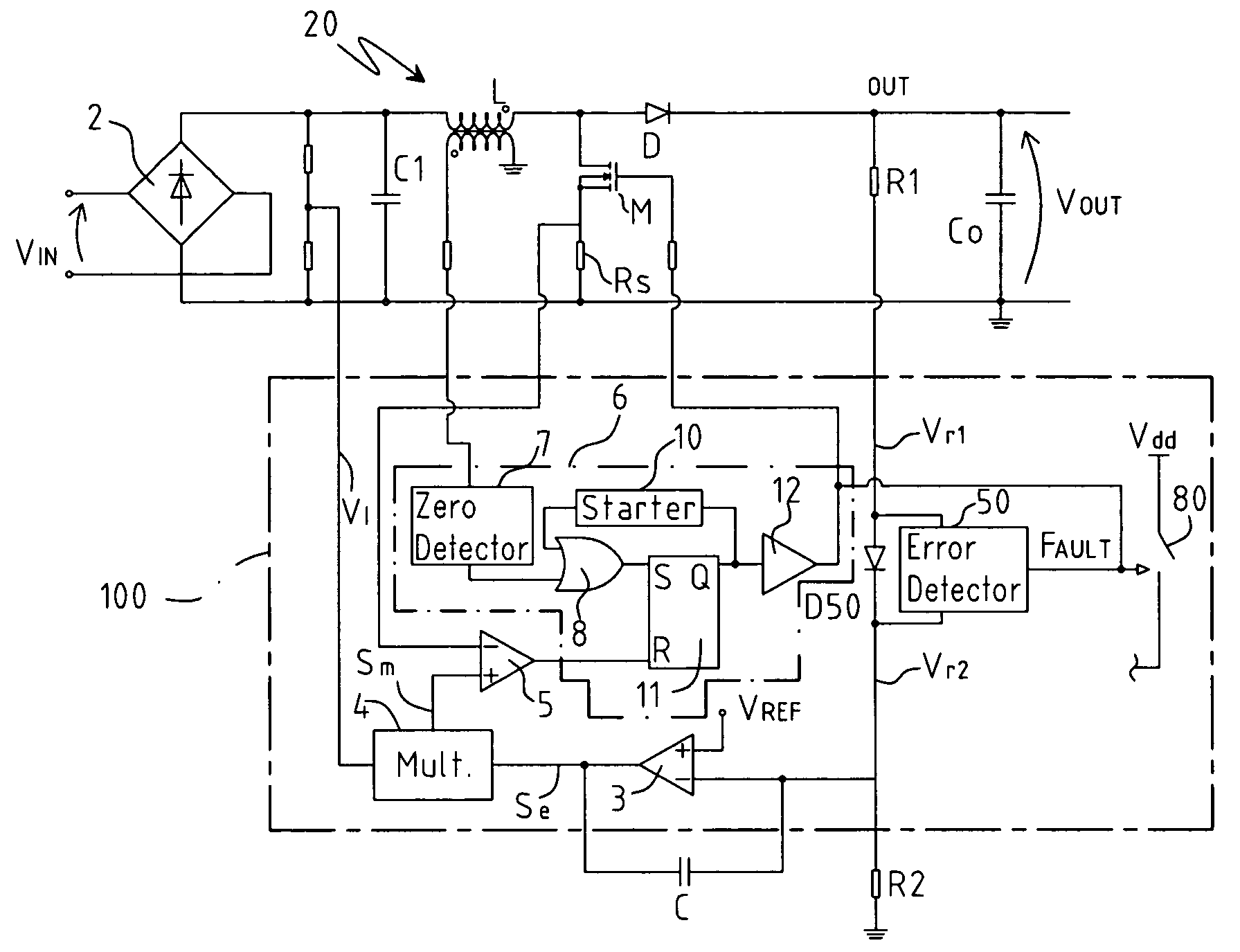
[0031]FIG. 3 shows a circuit diagram of a PFC for a forced switching power supply in accordance with the present invention; the elements the same as the circuit of FIG. 1 will be indicated with the same references. The PFC comprises a converter 20 fitted with a full wave diode rectifier bridge 2 having in input a mains voltage Vin, a capacitor C1 (that serves as filter for the high frequency) having a terminal connected to the diode bridge 2 and the other terminal connected to ground, an inductance L connected to a terminal of the capacitor C1, a MOS power transistor M having the drain terminal connected to a terminal of the inductance L downstream from the latter and having the source terminal connected to a resistance Rs connected to ground, a diode D having the anode connected to the common terminal of the inductance L and of the transistor M and the cathode connected to the output terminal Out of the PFC; a capacitor Co is also present connected between the terminal Out and grou...

second embodiment

[0049]In FIG. 7 circuit comprising the diode D50 and the circuit block 50 is shown. The latter comprises a first comparator 62 having the inverting terminal, on which the voltage Vr1 is present, connected to the anode of the diode D50 and the non-inverting terminal, on which the signal Vr2 is present, connected to the cathode of the diode D50 and a second comparator 63 having the inverting terminal, on which the signal Vr2 is present, connected to the cathode of the diode D50 and the non-inverting terminal connected to a reference voltage Vt1 lower than Vref. The outputs of the comparators 62 and 63 are in input to an OR gate 64 whose output signal represents the set signal of a set-reset flip-flop 65; the latter generates in output the signal Fault for the deactivation of the control circuit 100 and for the turn-off of the transistor M. A current generator I50, which generates a current of a smaller value than the current that flows through the diode D50 and that is of approximatel...


PUM


Abstract

A device corrects the power factor in forced switching power supplies and includes a converter and a control device to obtain a regulated voltage on an output terminal. The control device comprises an error amplifier having an inverting terminal (Vout) and a non-inverting terminal receiving a reference voltage. The device includes first and second resistances coupled in series with a conduction element positioned between the first resistance and the inverting terminal of the error amplifier and a fault detector suitable for detecting the electrical connection of the conduction element with the output terminal and suitable for detecting an output signal of the second resistance. The fault detector is suitable for supplying a malfunction signal upon detecting an electric disconnection of the conduction element from the output terminal or when the output signal of the second resistance tends to zero.

Description

BACKGROUND OF THE INVENTION[0001]1. Field of the Invention[0002]The present invention refers to a device for the correction of the power factor in forced switching power supplies.[0003]2. Description of the Related Art[0004]The use of power factor correction (PFC) devices for the active correction of the power factor (PF) for forced switching power supplies is generally known when used in electronic appliances of common use such as computers, television sets, monitors, etc. and also for the supply of fluorescent lamps, that is of forced switching pre-regulator stages whose task is to absorb current from the mains supply that is almost sinusoidal and is in phase with the mains voltage. Therefore a forced switching power supply of the current type comprises a PFC and a DC-DC converter connected to the output of the PFC.[0005]A forced switching power supply of the traditional type comprises a DC-DC converter and an input stage connected to the distribution mains supply of electrical en...

Claims


Application Information

Patent Timeline
Patent Type & Authority Patents(United States)
IPC IPC(8): H02H7/12G05F1/70H02M3/335H02M1/00H02M1/32H02M1/42
CPCH02M1/32H02M1/4225Y02B70/126Y02B70/10
Inventor ADRAGNA, CLAUDIOFAGNANI, MAUROMORICONI, UGO
Owner STMICROELECTRONICS SRL
Why Eureka
Try Eureka