Controller system for pool and/or spa

a control system and pool technology, applied in the direction of process and machine control, testing circuits, instruments, etc., can solve the problems of stand alone systems, wiring mistakes, and maintaining the level of water, so as to facilitate the testing of proper ground fault operation, reduce installation costs of control systems, and protect ground faults.

Inactive Publication Date: 2008-10-21
DYMAS FUNDING COMPANY
View PDF3 Cites 61 Cited by
  • Summary
  • Abstract
  • Description
  • Claims
  • Application Information

AI Technical Summary

Benefits of technology

[0010]A control system for a pool and spa installation is described, which provides for a simplified installation with effective ground fault protection. Main line voltage service for the pool and spa equipment is provided through a single line voltage service and a single ground fault circuit interrupter (GFCI) device. The control system acts as a distribution system for controlling the pool and spa equipment, with a circuit board assembly including individual circuit protection devices and switching circuits. Because the primary line voltage supply is through a single GFCI, testing of proper ground fault operation is facilitated through a ground fault test. Moreover, the installation costs of the control system are substantially reduced over those of conventional, pool controller systems, because many of the wiring connections are made on the circuit board assembly.
[0017]Another aspect of the invention is in an improved temperature sensor for sensing air or water temperature. Parallel variable resistance elements such as thermistors are incorporated in a common housing to provide separate temperature sensing circuits which can be read by the system controller. The use of multiple sensing circuits provides redundancy, and provides two temperature readings which are monitored by the controller.

Problems solved by technology

This is a time consuming task, and one which can lead to wiring mistakes, in view of the number of wiring connections which need to be made.
A problem with pools is maintaining the level of water within the pool.
Stand alone systems for doing this are known, but tend to be somewhat complex.
This heater is typically gas-operated, and does not operate properly when the gas pressure is too low.
Power loads imposed by the pool system's electrical components can be considerable.

Method used


Image

  • Controller system for pool and/or spa
  • Controller system for pool and/or spa
  • Controller system for pool and/or spa

Examples


Embodiment Construction

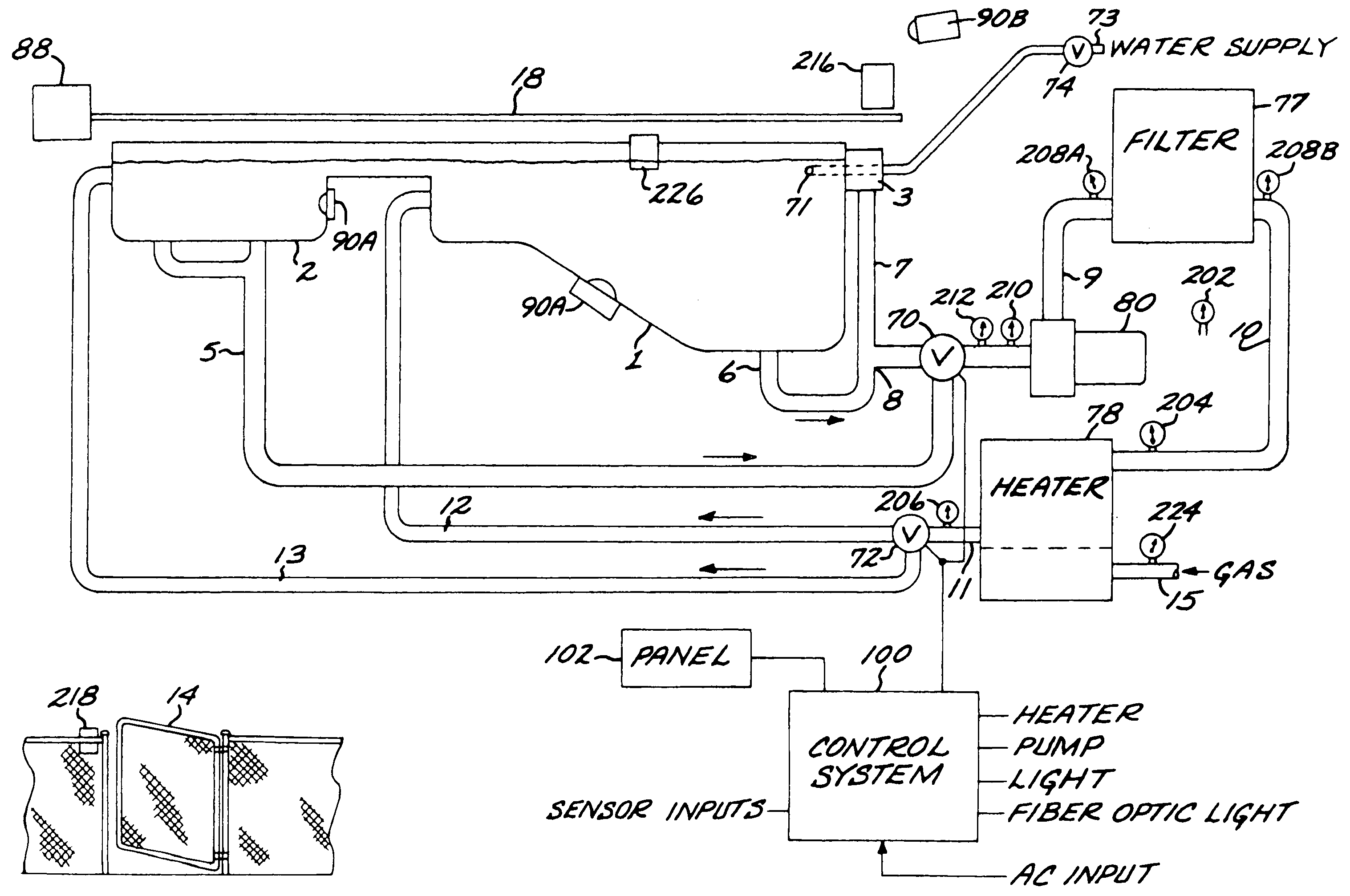
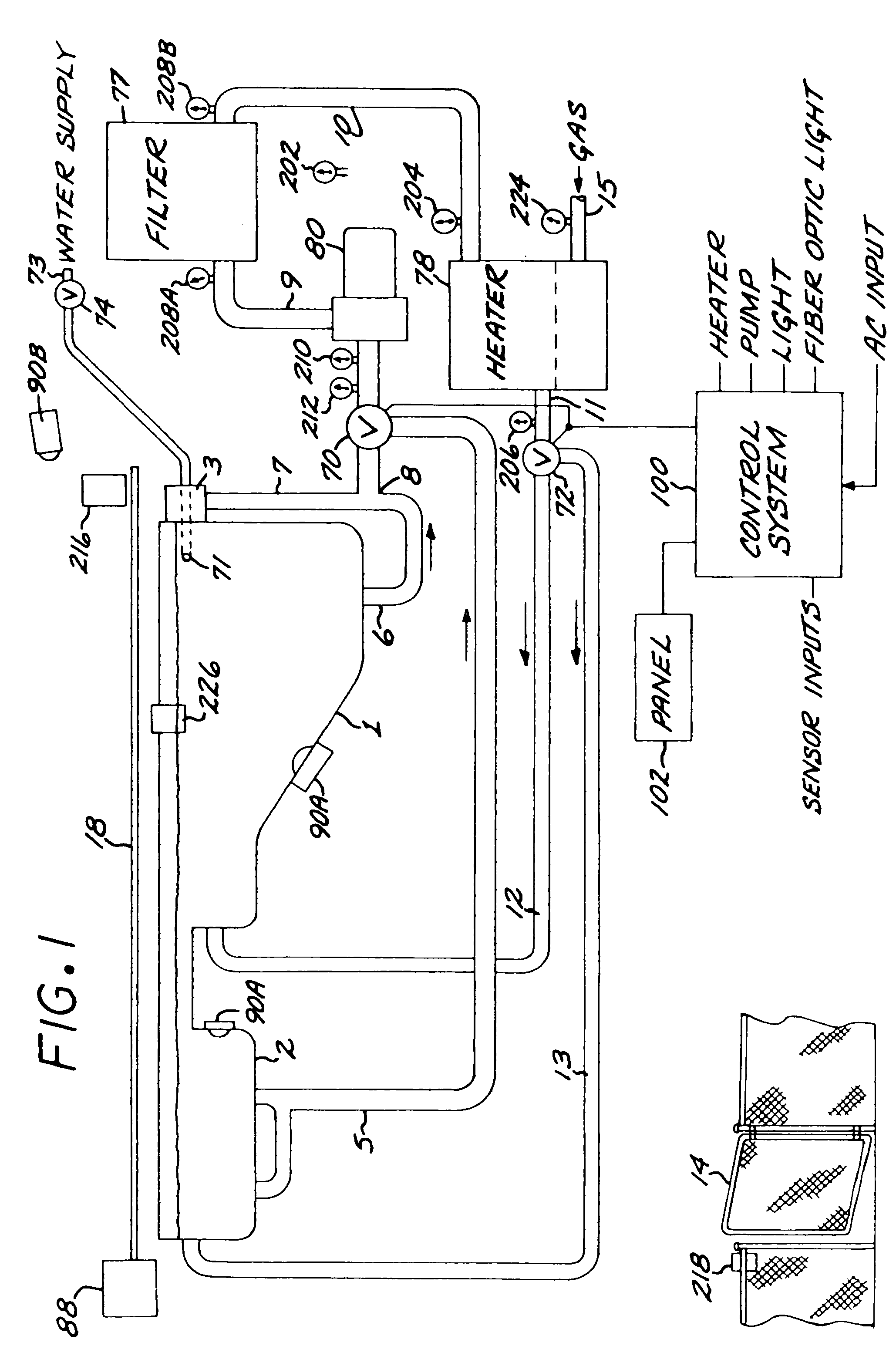
[0041]FIG. 1 is a diagrammatic view of a pool and spa system utilizing aspects of this invention. In this embodiment, the pool 1 and spa 2 share filter 77 and heater 78 through a plumbing arrangement including three-way valves 70 and 72, although other arrangements can be employed, such as separate heaters and filters for the pool 1 and spa 2. A conventional skimmer 3 is included, and its drain line 7 and the pool drain line 6 are joined at a junction tee before connection to one input of the valve 70. The drain line 5 from the spa is connected to the other input of valve 70. The valve output is connected to the input side of the filter pump 80 through water line 8. A water line 9 runs from the pump output to the filter input. The filter output is connected by water line 10 to the heater input. The heater output 11 is connected to the input of the three-way valve 72. One output of the valve is connected to water line 12 leading to a pool inlet. The other output of valve 72 is connec...


PUM


Abstract

A method of programming a microcomputer based controller system for a bathing installation. The microcomputer is configured to receive input command and sensor information from a plurality of input devices including a control panel and a bathing installation sensor, and acts on the input information operating according to a program running on the microcomputer which performs control functions for a plurality of bathing installation functions, including operating a water heater and a water pump of the bathing installation.

Description

[0001]This is a divisional application of application Ser. No. 10 / 066,869 filed Feb. 4, 2002 now U.S. Pat. No. 6,747,367, which in turn was a division of application Ser. No. 09 / 451,561, filed Nov. 30, 1999, now U.S. Pat. No. 6,407,469.TECHNICAL FIELD OF THE INVENTION[0002]This invention relates to controller systems for pools and spas.BACKGROUND OF THE INVENTION[0003]Electronic control systems have been employed to control various functions. Typically, however, the power hookups for the different components associated with the pool or spa have been run directly through circuit breakers in a main or auxiliary panel to the various components, such as the pump, heater and lights. This is a time consuming task, and one which can lead to wiring mistakes, in view of the number of wiring connections which need to be made. There is therefore a need to simplify the power hookups to the various components, in order to control costs and provide more reliable installations.[0004]A problem with...

Claims


Application Information

Patent Timeline
Patent Type & Authority Patents(United States)
IPC IPC(8): G01R31/00G06F19/00A61H33/00H05K1/02
CPCA61H33/005A61H33/0087A61H33/60A61H2201/0173A61H2201/0176H05K1/0263A61H33/00A61H2201/50A61H2201/5082
Inventor OTTO, CINDY
Owner DYMAS FUNDING COMPANY
Why Eureka
Try Eureka