Schematic generation

a technology of schematics and grids, applied in the field of schematic generation, can solve the problems of unsuitable use of small devices such as mobile phones and pdas, mobile devices usually have small screens with limited capacity for representing complex geographical information, etc., and achieve the effect of simplifying graphical data

Inactive Publication Date: 2008-10-21
M SPATIAL
View PDF37 Cites 61 Cited by
  • Summary
  • Abstract
  • Description
  • Claims
  • Application Information

AI Technical Summary

Benefits of technology

[0084]The modification algorithm may simplify the graphical data for example by adjusting the relative positions of nodes or relative angles of edges in the graphical data.
[0085]An advantage of this aspect is that a variety of different schematics can be generated from a common set of source data. Also, the format and / or content of the schematics can be customised for a particular user or output device.

Problems solved by technology

Conventional World-Wide Web based routing and guidance services provide information geared to large-screen devices such as computer terminals, but are generally unsuitable for use with small devices such as mobile phones and PDAs.
Mobile devices usually have small screens with limited capacity for representing complex geographical information such as maps.

Method used


Image

  • Schematic generation
  • Schematic generation
  • Schematic generation

Examples


example

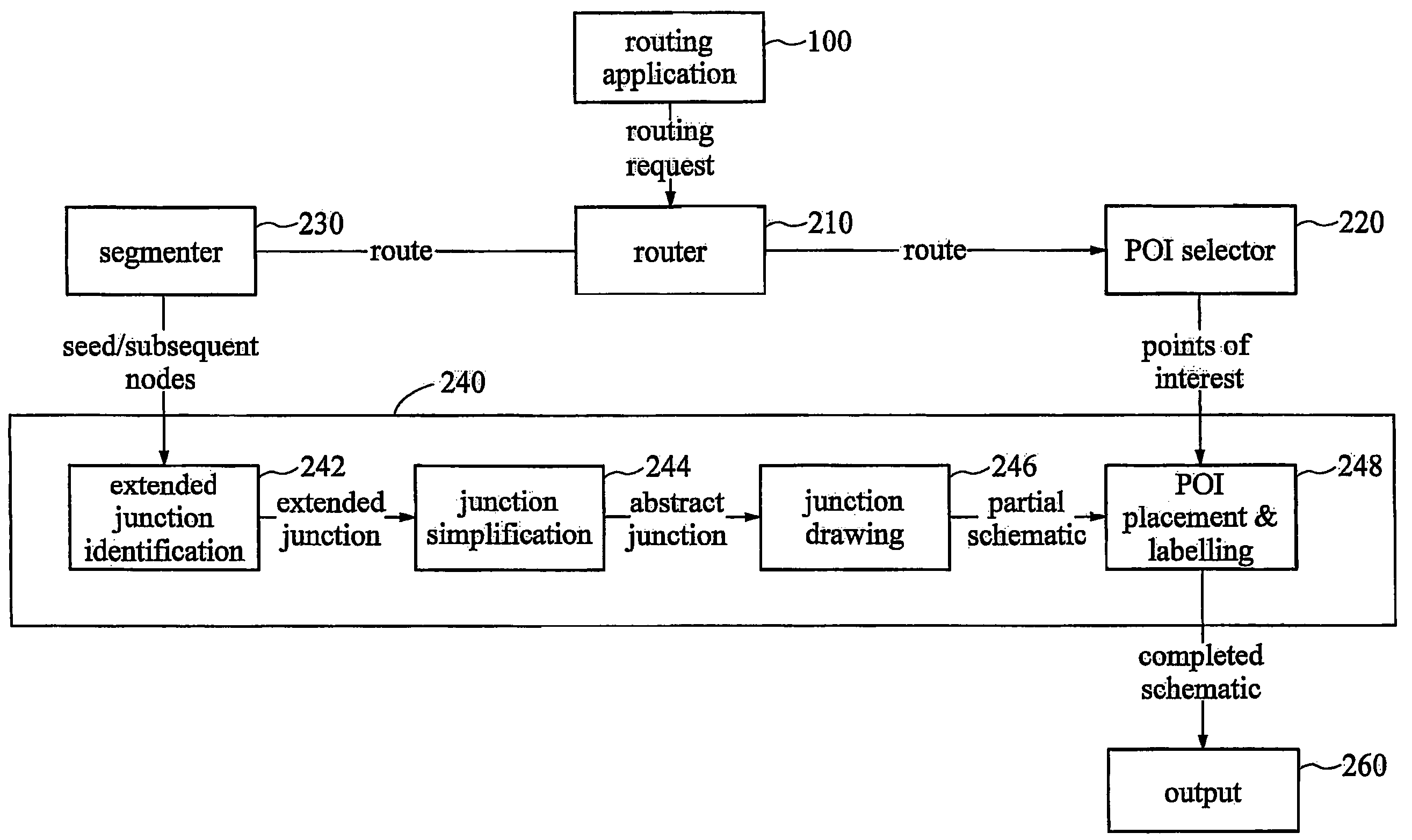
[0491]Referring once again to the sample network data illustrated in FIG. 17, as an example of how the clumping algorithm works, consider an extended junction comprising nodes F, E and A.

[0492]FIG. 21 shows this extended junction with exits labelled. Since external junction edges EG and AB are flagged in the source data as being two sides of the same dual carriage way, these are identified as the same exit by the junction simplification module.

[0493]Therefore, FIG. 21 shows a total of 4 exits labeled e1, e2, e3 and e4.

[0494]In the first step of clump identification, the exits are considered to determine which exits need to be assigned to separate clumps. In the example, e3 and e4 are assigned to two separate clumps C1, and C2, since they are near parallel. At this stage, exits e1 and e2 are yet to be assigned to clumps.

[0495]In the second step, the remaining edges are considered. Exit e1 cannot belong to the clump c1 (so far containing e3) since it is near anti-parallel with e4 (in ...


PUM


Abstract

A method of generating data representative of a geographical network (such as a road network) is disclosed, comprising steps of selecting from a database (2) data relating to an extended junction (formed from at least one node at least one edge) and outputting the selected data. The method address problems in existing devices relating to the selection of appropriate data, and finds particular application in the field of mobile devices and the like. Apparatus for generating data representative of a geographical network and a method of providing a graphical schematic of a location are also disclosed.

Description

PRIOR APPLICATION DATA[0001]The present application is a national phase application of International Application PCT / GB03 / 00297, entitled “SCHEMATIC GENERATION” filed on Jan. 23, 2003, which in turn claims priority from United Kingdom application 0201517.0, filed on Jan. 23, 2002, and United Kingdom application 0227466.0, filed on Nov. 25, 2002, and United Kingdom application 0227466.8, filed on Nov. 25, 2002, all of which being incorporated by reference in their entirety.FIELD OF THE INVENTION[0002]The invention relates to a method of and apparatus for generating data representative of a geographical network and a method of providing a graphical schematic of a location. The invention finds particular application in the field of routing services for mobile devices.BACKGROUND OF THE INVENTION[0003]Conventional World-Wide Web based routing and guidance services provide information geared to large-screen devices such as computer terminals, but are generally unsuitable for use with smal...

Claims


Application Information

Patent Timeline
Patent Type & Authority Patents(United States)
IPC IPC(8): G06F17/50G01C21/32G01C21/00G01C21/20G09B29/00G01C21/36G08G1/137G09B29/10H04M3/42H04M3/487
CPCG01C21/20G01C21/343G01C21/3476G01C21/3655H04M3/4872H04M2242/14H04M2242/30
Inventor CUTHBERT, ADRIANHAGGER, MARKBOWDITCH, NIGELBILLING, JONWALKER, JAMES ANDREWLUK, KAI
Owner M SPATIAL
Why Eureka
Try Eureka