Active thermal energy storage system

a technology of active heat storage and energy storage, which is applied in the direction of air heaters, domestic heating, solid-state devices, etc., can solve the problem of providing this energy

Inactive Publication Date: 2008-10-28
ELCAL RES LLC
View PDF3 Cites 35 Cited by
  • Summary
  • Abstract
  • Description
  • Claims
  • Application Information

AI Technical Summary

Benefits of technology

[0010]In one example, systems exist for collecting solar energy from the sun's radiation only during the limited day time hours for use in home air or water heating needs. However, such systems can only provide this energy when the sun is available. During the evening hours or on cloudy days the residential dwelling and / or commercial building air and / or water heating energy needs must be obtained from or supplemented by other available sources of energy, such as oil, natural gas, wind or electrical energy. Thus, alternative sources of energy are required in order to satisfy the full 24 hours of energy needs. The ATESS functions to receive solar energy during daylight hours, and to store that energy in a thermal energy storage material for use at any time during a 24 hour period. Stored energy is then transferred to the area of need by an active heat transfer (e.g., heat pump) system. In this way, the ATESS can make solar energy available 24 hours a day, thus reducing the need for oil or natural gas for residential dwelling and / or commercial building heating and / or water heating energy needs.
[0013]The ATESS will reduce markedly the daytime peak power electric demands on the electrical power grid and the electric generating equipment of the local power companies. The ATESS enables more efficient local use of energy from the local power grid, thus reducing or eliminating the need for oil and natural gas. Concurrent reductions in the emission of carbon dioxide and other pollutants, normally associated with energy production from oil or natural gas, would also be achieved.

Problems solved by technology

However, such systems can only provide this energy when the sun is available.

Method used


Image

  • Active thermal energy storage system
  • Active thermal energy storage system
  • Active thermal energy storage system

Examples


Embodiment Construction

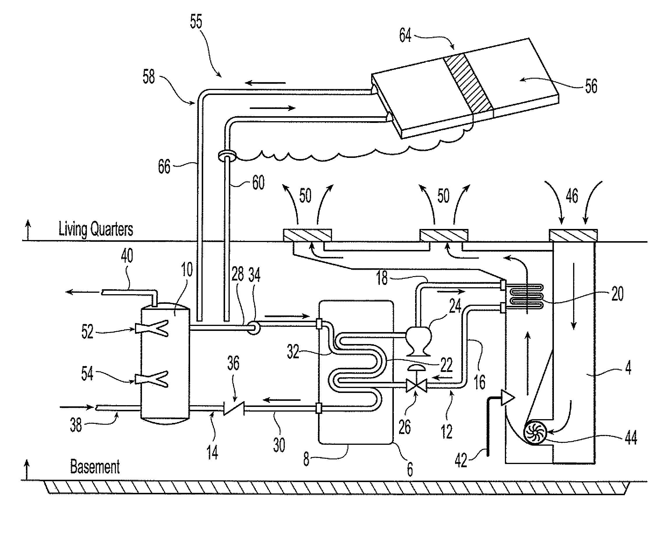
[0028]As previously noted, there are many sources of energy (e.g., solar, electrical, oil, gas, wind, etc.) which may be available for collection only during limited time periods during a 24 hour day. This is in contrast to the electrical, heating or cooling power needs associated with a residential or commercial building, which may vary during any given 24 hour period. The disclosed ATESS accommodates such limited availability of these energy sources and provides a steady source of energy, as needed, throughout a 24 hour period.

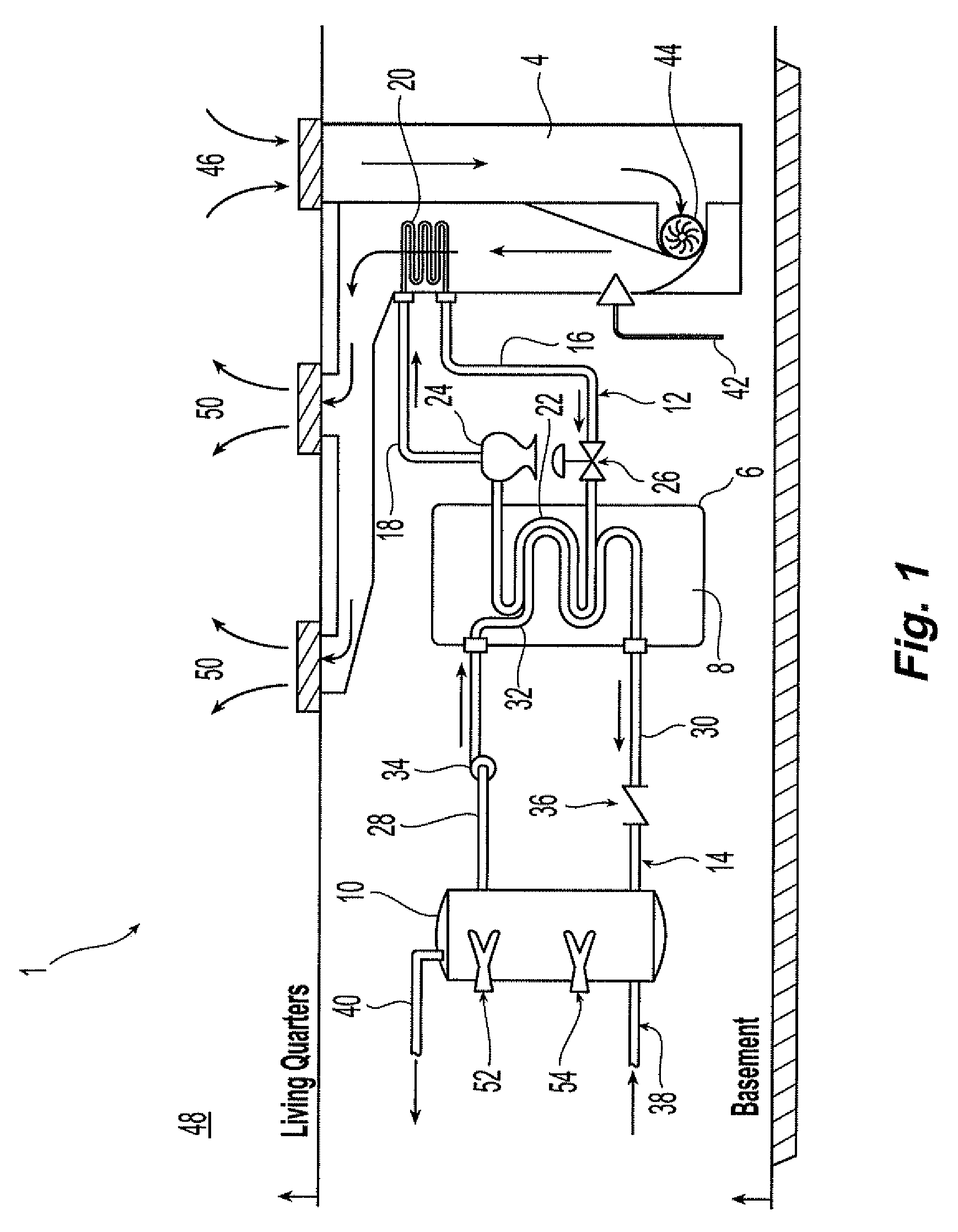
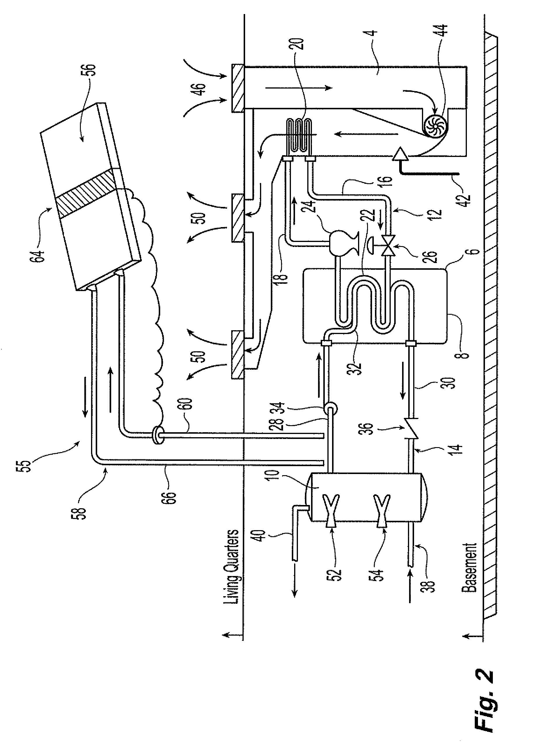
[0029]Referring to FIG. 1, the ATESS 1 is shown installed in the basement area 2 of a dwelling having an oil or natural gas hot air furnace system 4. The ATESS 1 may comprise a storage tank 6 containing a quantity of thermal energy storage material 8, a hot water storage tank 10 for heating and distribution of hot water through the residence, and a connection 12 between the storage tank 6 and the furnace system 4 to allow the transfer of heat between the the...


PUM

PropertyMeasurementUnit
melting pointaaaaaaaaaa
volumeaaaaaaaaaa
inner volumeaaaaaaaaaa

Abstract

An active thermal energy storage system is disclosed which uses an energy storage material that is stable at atmospheric pressure and temperature and has a melting point higher than 32 degrees F. This energy storage material is held within a storage tank and used as an energy storage source, from which a heat transfer system (e.g., a heat pump) can draw to provide heating of residential or commercial buildings and associated hot water. The energy storage material may also accept waste heat from a conventional air conditioning loop, and may store such heat until needed. The system may be supplemented by a solar panel system that can be used to collect energy during daylight hours, storing the collected energy in the energy storage material. The stored energy may then be used during the evening hours to heat recirculation air for a building in which the system is installed.

Description

CROSS-REFERENCE TO RELATED APPLICATIONS[0001]This is a U.S. non-provisional application of pending U.S. provisional patent application Ser. No. 60 / 852,844, filed Oct. 19, 2006 by Leslie Leifer et al., titled “Active Thermal Energy Storage System,” the entire contents of which application is expressly incorporated herein by reference.FIELD OF THE INVENTION[0002]The invention relates to a system for heating and cooling of residential and commercial building spaces and hot water systems, and more particularly to an active heat transfer system used for use in efficiently controlling air and water temperature in commercial buildings and residences.BACKGROUND OF THE INVENTION[0003]The electrical energy generation and distribution networks in the United States are currently stressed to the limit by peak demands during daytime hours. Quite expectedly, the demands of the industrial sector, commercial and residential air conditioning and water heating are highest during the daytime hours. Dur...

Claims


Application Information

Patent Timeline
Patent Type & Authority Patents(United States)
IPC IPC(8): F24J2/34F24H7/00
CPCF24D11/0257F24F5/0017F24F5/0046F24F5/0096F28D20/0034F28D20/021F24D3/08F24D2200/08F24D2200/12F24D2200/14F24F2005/0064F28D2021/0019Y02B10/20Y02B10/24Y02B10/70Y02B30/126Y02E60/142Y02E60/145Y02E60/147Y02E70/30Y02B30/12Y02E60/14Y02A30/272Y02B30/13F24H7/00
Inventor LEIFER, LESLIEROWE, JAY D.
Owner ELCAL RES LLC
Why Eureka
Try Eureka