Conveyance system

a technology of conveying system and chain, which is applied in the direction of driving chains, gearing, hoisting equipment, etc., can solve the problems of difficult assembly work, and large pulsations and speed variations of chains, so as to improve riding comfort and facilitate disengagement , work can be carried out more effectively

Inactive Publication Date: 2008-10-28
TSUBAKIMOTO CHAIN CO
View PDF13 Cites 25 Cited by
  • Summary
  • Abstract
  • Description
  • Claims
  • Application Information

AI Technical Summary

Benefits of technology

[0014]With the sprocket teeth formed so the distance from the tooth center line to the front tooth surface at a location radially outward from the pitch circle is at least as great as the distance from the center line to the front tooth surface at the pitch circle, vertical movement of the chain resulting from polygonal motion is reduced, and pulsations and speed variations due to the polygonal motion are suppressed so that articles can be conveyed in a stable manner, work can be carried out more effectively on the conveyed articles, and riding comfort is improved.
[0015]Where the root diameter of the sprockets is smaller than the root diameter in a sprocket following the ISO tooth form standards, the rollers or bushings of the chain can be smoothly disengaged from the sprockets.

Problems solved by technology

However, because of the larger chain pitch, large pulsations and speed variations of the chain are generated due to polygonal motion.
These pulsations and speed variations are a problem in chain conveyors, especially in assembly lines for automobiles, electrical appliances and the like, where workers ride on the conveyor, and also in the case of escalators.
In the case of an assembly line conveyor, pulsations and speed variations make assembly work difficult.
Moreover, in the case of an assembly line conveyor, and in an escalator as well, the pulsations and speed variations result in an uncomfortable ride.
In the case of an escalator, a smaller chain pitch has been used in order to improve rider comfort, but the smaller chain pitch results in significantly increased costs because of the high parts count.

Method used


Image

  • Conveyance system
  • Conveyance system
  • Conveyance system

Examples


first embodiment

[0033]The sprocket 11, in accordance with the invention, has a tooth form as shown in FIG. 4, each tooth 15 having opposite tooth surfaces 12a and 12b.

[0034]The teeth 15 are separated by tooth gaps 14, and the front tooth surface 12a of each tooth, and the facing back tooth surface 12b of a next tooth are continuous with the bottom of a tooth gap between the teeth.

[0035]Further, in the tooth form shown in FIG. 4, the front tooth surface 12a and the back tooth surface 12b are symmetrical with respect to the center line x of the tooth 15, which is a radial line extending from rotational center O of the sprocket 11 (see FIG. 3) and the center of the root of the tooth 15.

[0036]As seen in FIG. 4, the tooth surfaces 12a and 12b are both in the form of a concave curved surface. Moreover, the tooth bottom 13 is in the shape of an arc having a radius ri13 centered on the pitch circle pc. The concave tooth surfaces 12a and 12b are smoothly continuous with the arcuate tooth bottom.

[0037]The d...

second embodiment

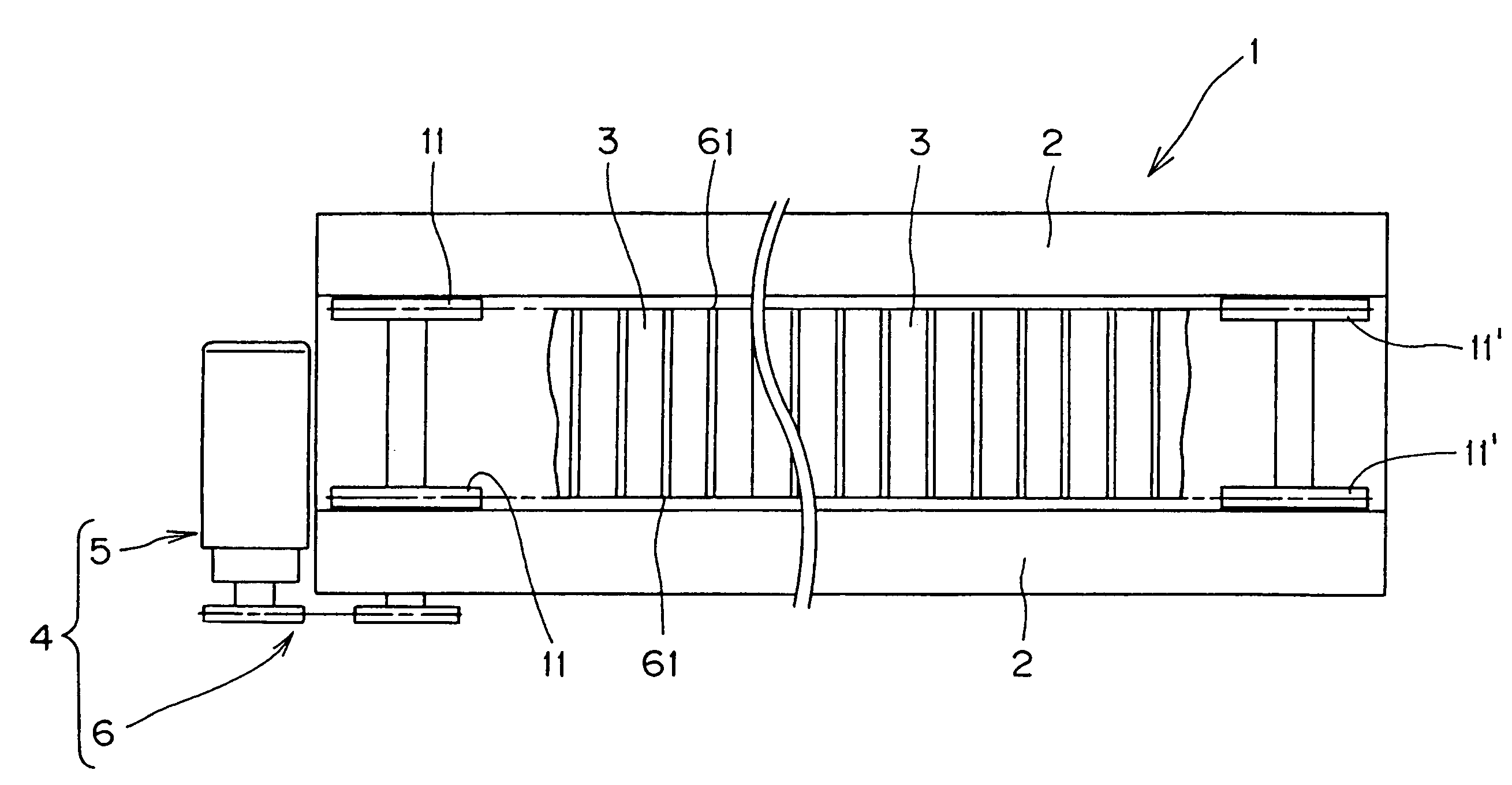
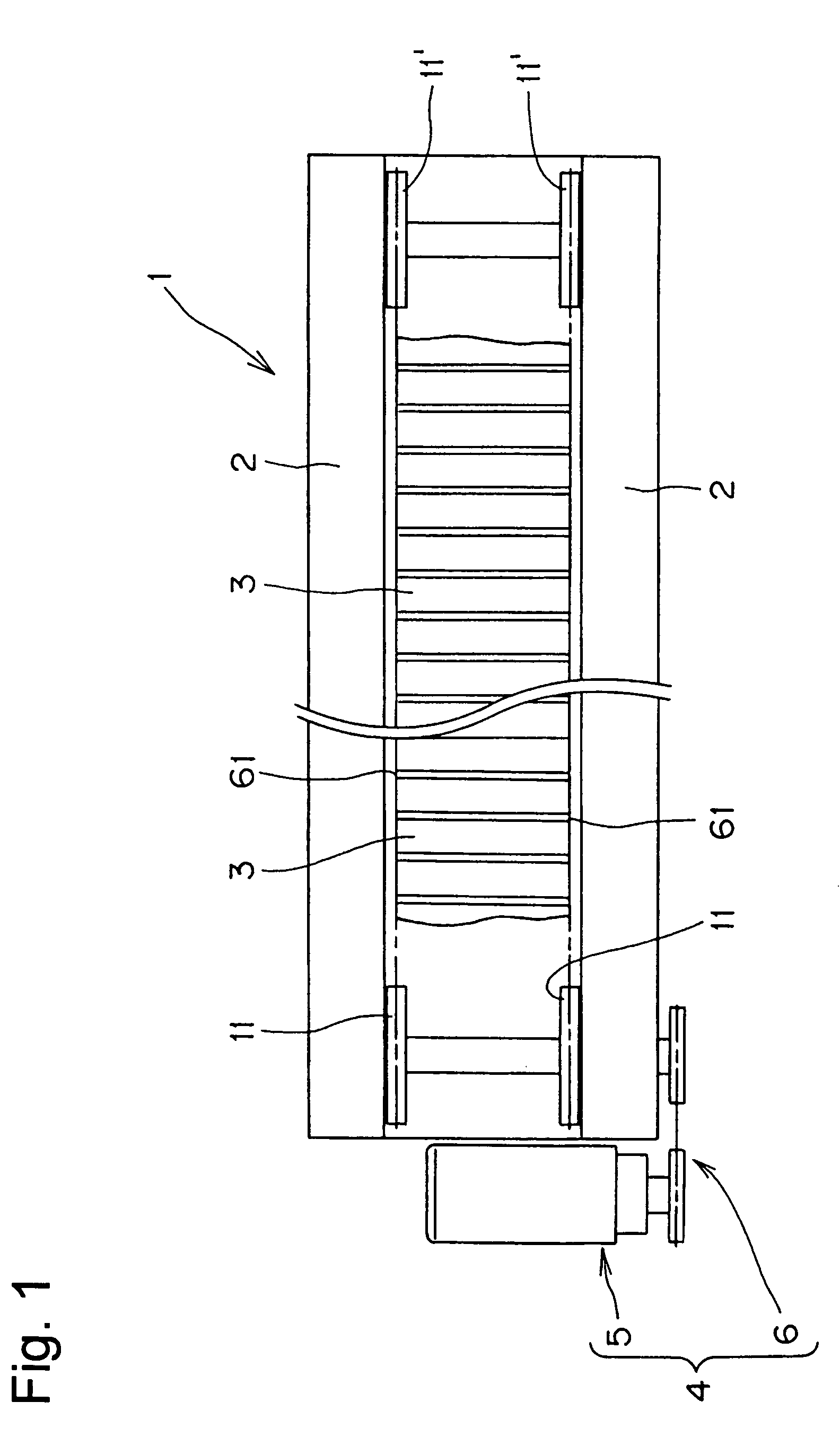
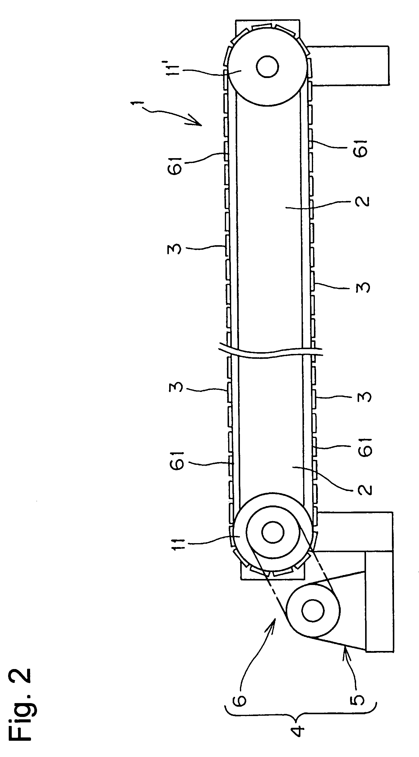
[0043]In a slat conveyor according to the invention, the driving and driven sprockets have the tooth configuration shown in FIG. 7. Since the driving and driven sprockets have the same tooth forms, only the driving sprocket 21 will be described.

[0044]Each tooth 25 has front and back tooth surfaces 22a and 22b respectively, and the teeth are separated by tooth gaps 24, having a tooth gap bottom 23 which is smoothly continuous with the facing front and back surfaces of adjacent teeth. The front tooth surfaces 22a and the back tooth surfaces 22b are symmetrical with respect to the center lines x of the teeth 25. The tooth surface 22a and the tooth surface 22b are each in the form of a convex curved surface. The tooth bottom 23 is arc-shaped, with a radius ri23. The tooth surfaces 22a and 22b are smoothly continuous with the tooth bottom 23.

[0045]The distances from the center line x of the tooth 25 to the front tooth surface 22a in the rotational direction of the sprocket, and also from...

third embodiment

[0048]In a slat conveyor according to the invention, the driving and driven sprockets have the tooth forms shown in FIG. 8. Since the driving and driven sprockets have the same tooth forms, only the driving sprocket 31 will be described.

[0049]Each tooth 35 has front and back tooth surfaces 32a and 32b respectively, and the teeth are separated by tooth gaps 34, having a tooth gap bottom 33 which is smoothly continuous with the facing front and back surfaces of adjacent teeth. The front tooth surfaces 22a and the back tooth surfaces 22b are symmetrical with respect to the center lines x of the teeth 35. In this embodiment, the tooth surface 32a and the tooth surface 32b are in the form of parallel planes. The tooth bottom 33 is arc-shaped, with a radius ri33. The tooth surfaces 32a and 32b are smoothly continuous with the tooth bottom 33.

[0050]In this embodiment, the distances from the center line x of the tooth 35 to the front tooth surface 32a, and to the back tooth surface 32b, are...


PUM


Abstract

In a slat conveyor, slats for supporting conveyed articles and personnel extend between two side-by-side, spaced, endless roller chains engaged with driving sprockets at one end of the conveying path and driven sprockets at the other end. At a location radially outward from the pitch circle, the distance between the front surface of the sprocket teeth to the tooth center line is at least as great as the distance from the centerline to the front surface at the pitch circle. The tooth faces merge smoothly with the tooth gap bottom, and the root diameter is smaller than the root diameter according to ISO standards.

Description

CROSS-REFERENCE TO RELATED APPLICATION[0001]This application claims priority based on Japanese patent application 2004-302799, filed Oct. 18, 2004. The entire disclosure of the Japanese patent application 2004-302799 is hereby incorporated by reference.FIELD OF THE INVENTION[0002]This invention relates to a conveyance system in which a conveyor includes pair of endless conveyor chains engaged with a pair of driving sprockets and a pair of driven sprockets.BACKGROUND OF THE INVENTION[0003]Chain conveyors are used in various applications, such as in vehicle assembly. In a conventional chain conveyor, sprockets are arranged on the left and right sides of the conveyor path, both at the front end and at the rear end of the conveyor. A first chain is engaged with the sprockets on the left side, and a second chain is engaged with the sprockets on the right side. The chains reverse their direction of travel as they pass over the sprockets at the front and rear ends of the conveyor. Slat pla...

Claims


Application Information

Patent Timeline
Patent Type & Authority Patents(United States)
IPC IPC(8): F16H55/30F16G1/28F16G5/20B65G23/06B66B23/02
CPCB65G23/06B66B23/022B66B23/026F16H55/08F16H55/30B66B23/02
Inventor KUBO, AIZOHISHIDA, HIROKISONODA, MASATOSHI
Owner TSUBAKIMOTO CHAIN CO
Why Eureka
Try Eureka