Impermanent biocompatible fastener

Inactive Publication Date: 2008-10-28
BOSTON SCI SCIMED INC
View PDF29 Cites 1172 Cited by
  • Summary
  • Abstract
  • Description
  • Claims
  • Application Information

AI Technical Summary

Benefits of technology

[0017]Because the heads of the aforementioned fastener are not made entirely of a bioabsorbable material, but rather, are made of an inner core of a non-bioabsorbable material and an outer coating of a bioabsorbable material, the thickness of the bioabsorbable material is less than it would otherwise be in a corresponding head made entirely out of the bioabsorbable material. Consequently, because of its reduced thickness, the bioabsorbable material becomes

Problems solved by technology

Although weight loss and/or prescription acid blockers are typically preferred treatment options for GERD, various surgical procedures have been devised to treat GERD where weight loss and/or prescription drugs are ineffective or impractical.
Due to the highly invasive nature of such surgery, complications and morbidity occur in a significant percentage of cases.
In addition, these procedures are time-consuming, often taking a number of hours to perform, and may leave disfiguring scars where the incisions were made.
Although these procedures are less invasive than those involv

Method used


Image

  • Impermanent biocompatible fastener
  • Impermanent biocompatible fastener
  • Impermanent biocompatible fastener

Examples


Example

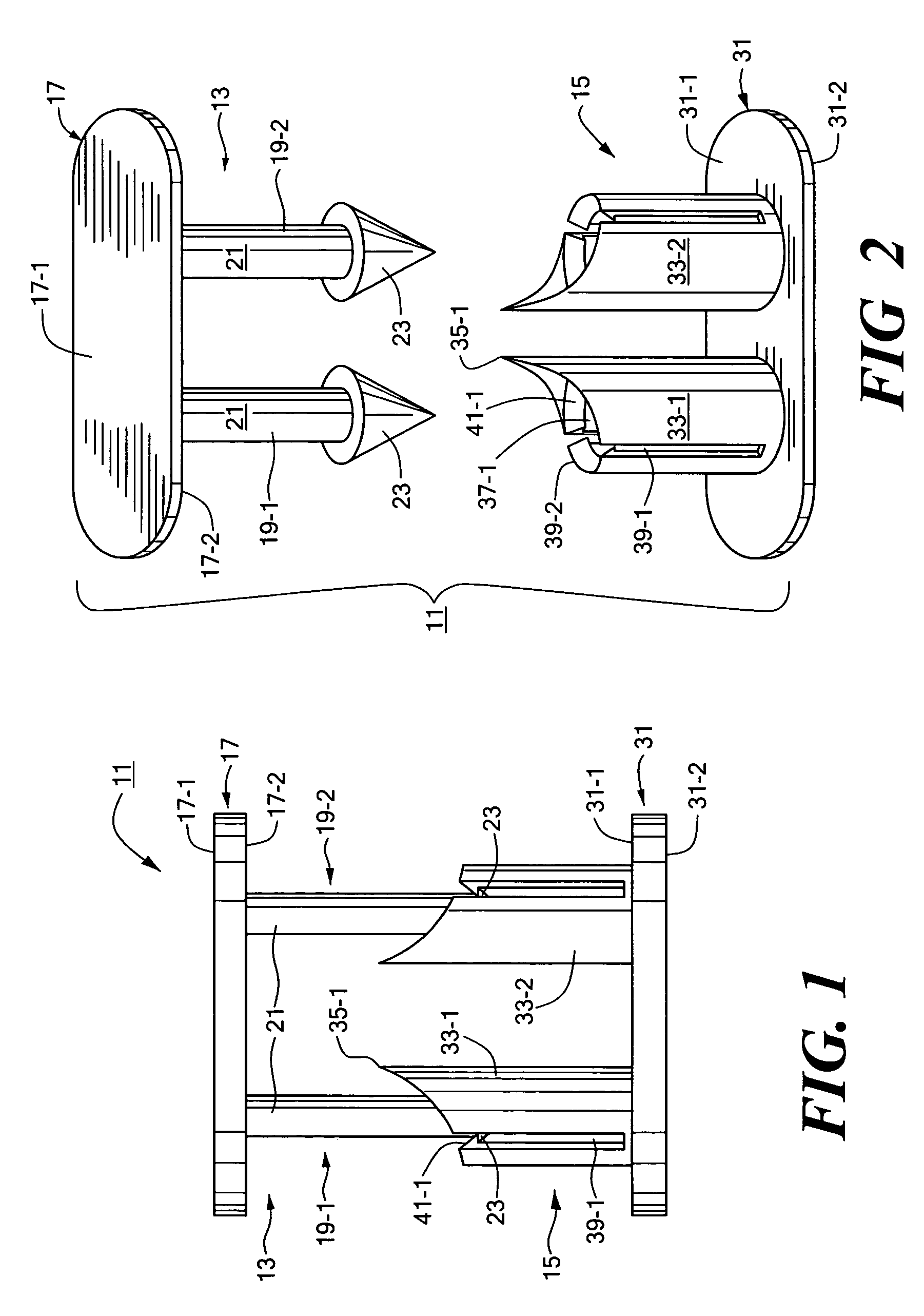
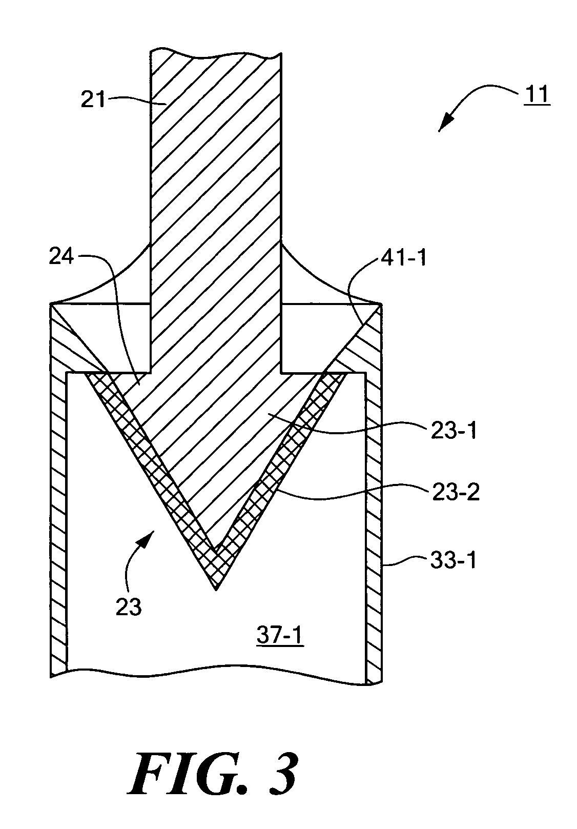
[0032]Referring now to FIGS. 1 through 3, there are shown various views of a first embodiment of a biocompatible fastener constructed according to the teachings of the present invention, said biocompatible fastener being represented generally by reference numeral 11.

[0033]Fastener 11, which is particularly well-suited for, but is not limited to, temporarily securing the gastric fundus to the esophagus as part of a fundoplication procedure, is a two-piece, mating-type fastener comprising a male portion 13 and a female portion 15.

[0034]Male portion 13, which may be made by molding, is a generally rigid structure comprising a base 17. Base 17, which is generally flat and oval, has a top surface 17-1 and a bottom surface 17-2. A pair of parallel male members 19-1 and 19-2 are disposed on opposite sides of the transverse centerline of base 17 and extend downwardly a short distance from bottom surface 17-2 of base 17. Male members 19-1 and 19-2 are substantially identical to one another, ...

Example

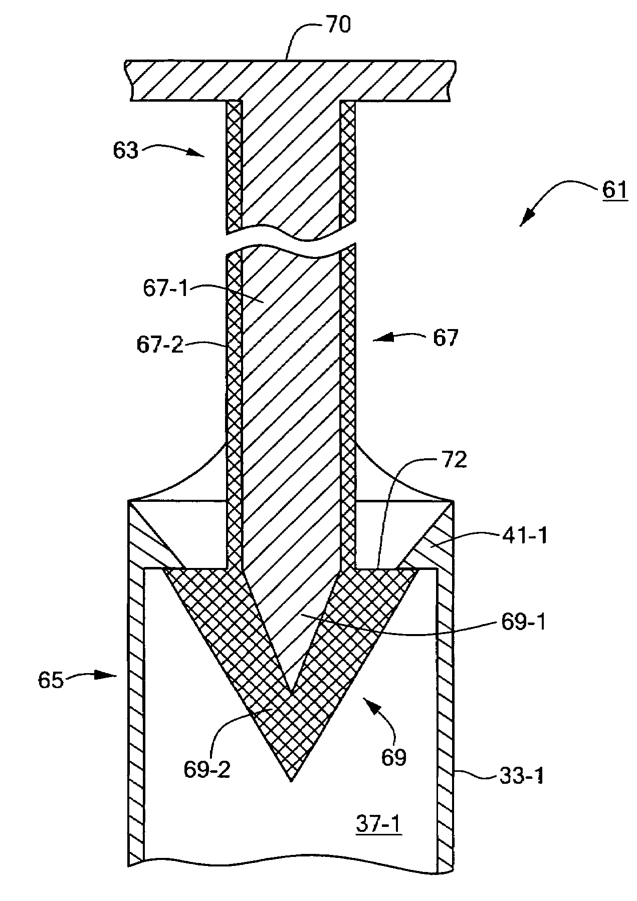
[0043]Referring now to FIG. 4, there is shown a fragmentary section view of a second embodiment of a biocompatible fastener constructed according to the teachings of the present invention, the biocompatible fastener being shown represented generally by reference numeral 61.

[0044]Fastener 61 is similar in many respects to fastener 11, fastener 61 comprising a male portion 63 and a female portion 65, male portion 63 being identical in overall size and shape to male portion 13 of fastener 11, female portion 65 being identical in all respects to female portion 15 of fastener 11.

[0045]The principal difference between fastener 61 and fastener 11 is that male portion 63 of fastener 61 is constructed to comprise, instead of a pair of posts 21 each terminating at its bottom end in a generally conical head 23, a pair of posts 67 each terminating at its bottom end in a generally conical head 69 (only one such post 67 and head 69 being shown and described herein although it is to be understood ...

Example

[0051]Referring now to FIG. 5, there is shown a fragmentary section view of a third embodiment of a biocompatible fastener constructed according to the teachings of the present invention, the biocompatible fastener being shown represented generally by reference numeral 81.

[0052]Fastener 81 is similar in many respects to fastener 61, fastener 81 comprising a male portion 83 and a female portion 85, male portion 83 being identical in overall size and shape to male portion63 of fastener 61, female portion 85 being identical in all respects to female portion 65 of fastener 11.

[0053]The principal difference between fastener 81 and fastener 61 is that the bottom portion of post 87 and the entirety of head 89 are made only of bioabsorbable material whereas the remainder of post 87 comprises a core 87-1 made out of a non-bioabsorbable material and a coating 87-2 made out of a bioabsorbable material having a desired degradation rate. As can readily be appreciated, the relative lengths of cor...


PUM


Abstract

A biocompatible fastener particularly well-suited for use in fundoplication procedures. In a preferred embodiment, the fastener is designed to break within the span of approximately three to six months after implantation and comprises a male portion and a female portion. The male portion includes a first base member, the first base member being generally flat and oval. A pair of male members are mounted on the bottom surface of the first base member, each male member comprising a cylindrical post extending downwardly from the bottom surface of the first base member and a conical head disposed at the bottom end of the post. The female portion includes a second base member, the second base member being generally flat and oval. A pair of sleeves are mounted on the top surface of the second base member and extend upwardly therefrom. Each sleeve defines a bore adapted to receive a head from a corresponding male member and has an inner flange formed thereon. The flange extends radially into the bore and is engageable with the head once the head has been inserted therepast so as to inhibit withdrawal of the head from the bore. Except for an outer coating on each of the two heads, the fastener is made entirely of a non-bioabsorbable material or a bioabsorbable material having a relatively slow degradation rate. By contrast, the outer coating is made of a bioabsorbable material having a relatively fast degradation rate. The thickness of the outer coating is appropriately selected so that degradation of the outer coating permits each head to be withdrawn past its flange after a desired period of time.

Description

CROSS-REFERENCE TO RELATED APPLICATIONS[0001]The present application is a continuation of U.S. patent application Ser. No. 09 / 935,950, filed Aug. 23, 2001, now U.S. Pat. No. 6,692,507 which is incorporated herein by reference.BACKGROUND OF THE INVENTION[0002]The present invention relates generally to biocompatible fasteners and more particularly to impermanent biocompatible fasteners.[0003]Biocompatible fasteners have long been used to fasten together two or more biological materials on or within a patient. Examples of biocompatible fasteners include sutures, staples, surgical glues, tissue clips and orthopedic fixation devices, such as bone plates, screws and the like. For certain applications, such as where the biocompatible fastener is implanted within a patient and is needed therewithin for only a limited period of time, it is highly desirable that the biocompatible fastener be impermanent or capable of degrading over time so that an additional medical procedure not be required ...

Claims


Application Information

Patent Timeline
IPC IPC(8): A61D1/00A61B17/56A61B17/00A61B17/08A61B17/064A61L17/00A61L24/00A61L27/00
CPCA61B17/0643A61B2017/00004
Inventor PUGSLEY, CHARLES H.LEVENDUSKY, JOSEPH A.
Owner BOSTON SCI SCIMED INC
Why Eureka
Try Eureka