
Charged particle beam apparatus

a technology of chargeable particles and beams, applied in the direction of material analysis using wave/particle radiation, instruments, nuclear engineering, etc., can solve the problems of difficult to instinctively comprehend the incident angle of the argon-ion beam with respect to the surface of the specimen, and difficult to precisely control the irradiation angle, etc., to achieve accurate and easy control of the irradiation angle of the gas-ion beam

Active Publication Date: 2008-10-28
HITACHI HIGH TECH SCI CORP
View PDF2 Cites 20 Cited by
  • Summary
  • Abstract
  • Description
  • Claims
  • Application Information

AI Technical Summary

Benefits of technology

The invention provides a charged particle beam apparatus that can accurately and easily control the angle at which a gas-ion beam is irradiated onto a sliced specimen. This is achieved by using a specimen posture recognition means to determine the position of the specimen in relation to the specimen stage, and calculating the amount of movement required to achieve the desired angle. The gas-ion beam can be irradiated onto the surface of the sliced specimen at the desired angle, either by using an observation image from a focused ion beam apparatus or a scanning electron microscope. The invention also allows for the use of different gas-ion beams, such as neon, argon, krypton, xenon, or nitrogen, and the placement of the gas-ion beam irradiation apparatus in a way that ensures accurate and easy irradiation of the surface of the sliced specimen at the desired angle.

Problems solved by technology

In order to fabricate a sliced specimen to be such particular minute portion, a focused ion beam apparatus is widely used, however, there arises a problem of damage by a focused ion beam as the required thickness of the specimen becomes thinner, and a method for preventing damage is needed.
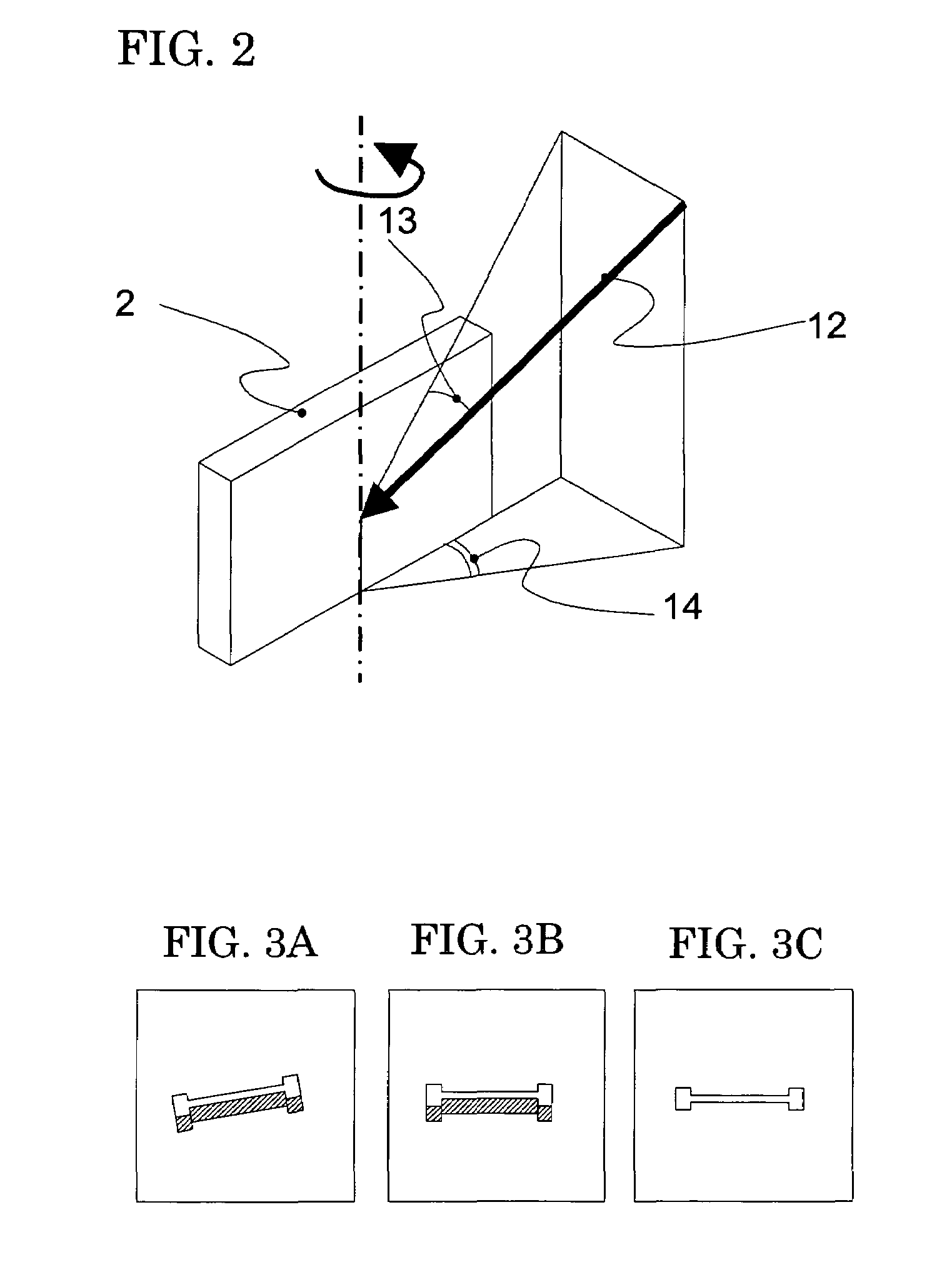
However, when the actual sliced specimen is inclined or bending with respect to the stage, the specimen cannot be recognized, therefore, there was a problem that it was difficult to precisely control the irradiation angle.
Therefore, it is difficult to instinctively comprehend the incident angle of the argon-ion beam with respect to the surface of the specimen 2.

Method used


Image

  • Charged particle beam apparatus
  • Charged particle beam apparatus
  • Charged particle beam apparatus

Examples


embodiment 1

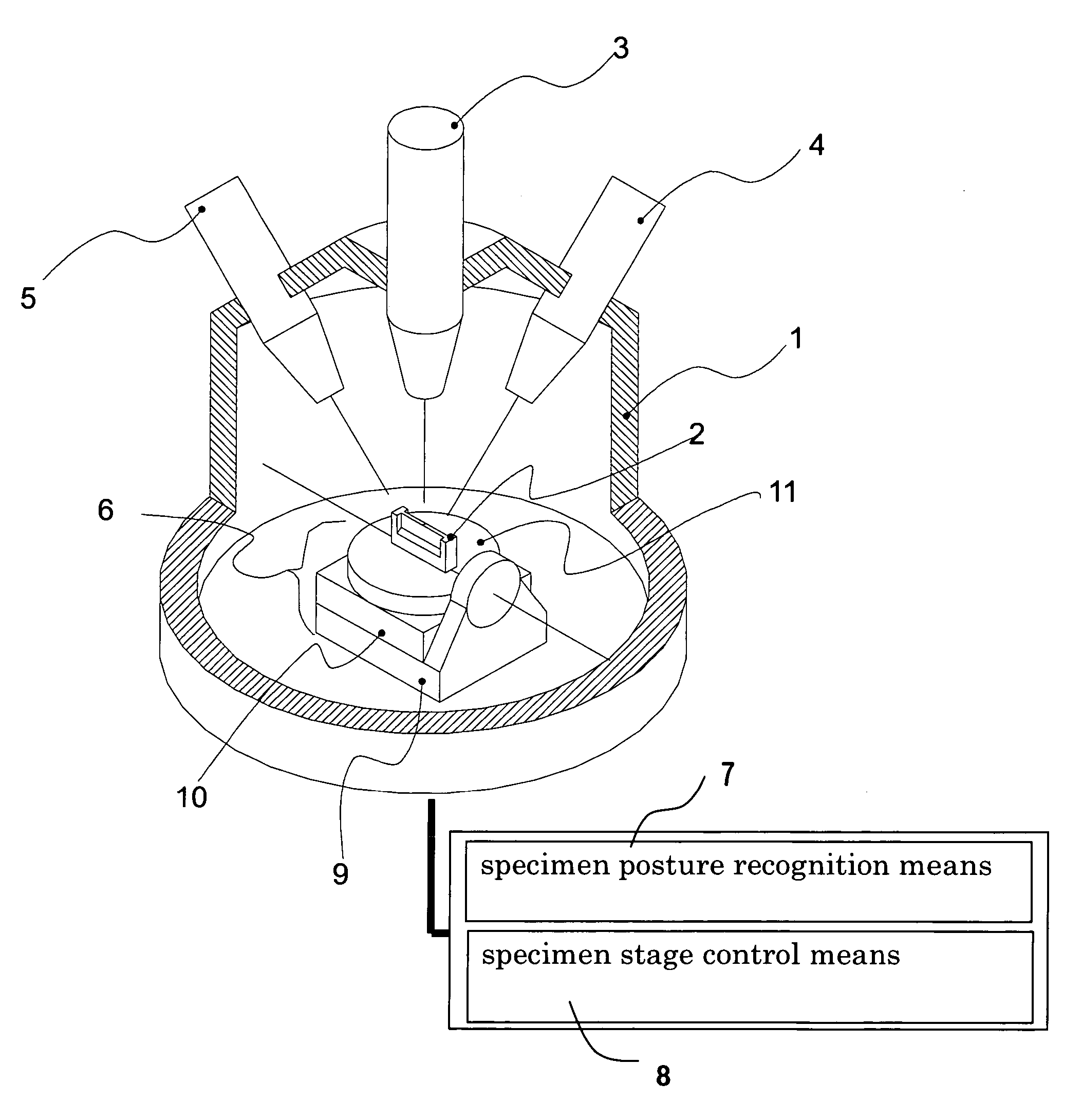
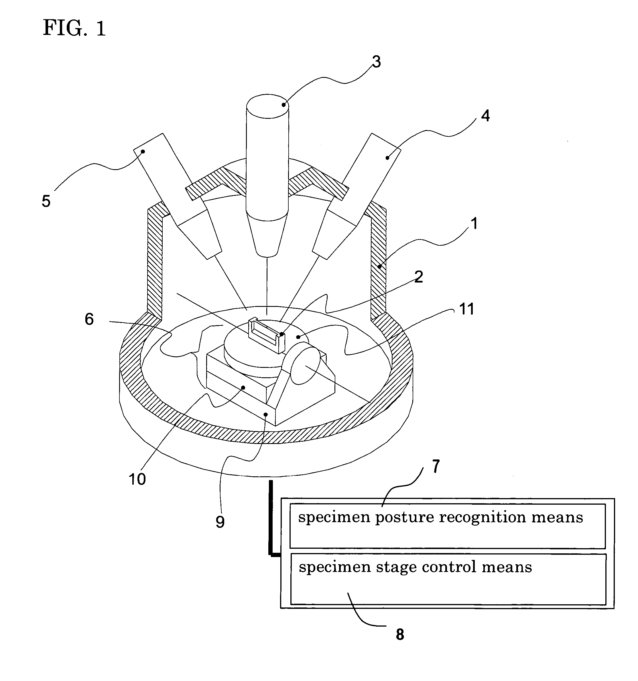
[0032]FIG. 1 is a schematic view showing an outline of a charged particle beam apparatus according to an embodiment 1 of the invention. In the embodiment, the explanation will be made on the assumption that a specimen is fixed on a stage as the specimen (hereinafter, referred to as a sliced specimen) which has been sliced to some degree using a focused ion beam apparatus and the like. Though omitted in FIG. 1, the sliced specimen is fixed on a specimen stage called as a “mesh” which is used when observed by TEM and fixed on a specimen stage 6 through the mesh. The meaning of “to be sliced to some degree” differs greatly depending on a specimen, an observation object thereof or the like, however, the thickness of the specimen is not related to the essence of the invention. To cite one example, the specimen which is sliced to the thickness of approximately 100 to 200 nanometers is used.

[0033]As shown in FIG. 1, the charged particle beam apparatus according to the embodiment includes, ...


PUM


Abstract

To include a focused ion beam apparatus fabricating a sliced specimen by processing a specimen as well as observing the sliced specimen, a scanning electron microscope observing the slice specimen, a gas-ion beam irradiation apparatus performing finishing processing by irradiating a gas-ion beam onto a surface of the sliced specimen, a specimen stage on which the sliced specimen is fixed and having at least one or more rotation axis, a specimen posture recognition means recognizing positional relation of the sliced specimen with respect to the specimen stage and a specimen stage control means controlling the specimen stage based on a specimen posture recognized by the posture recognition means and an installation angle of the gas-ion beam irradiation apparatus in order to allow an incident angle of the gas-ion beam with respect to the obverse or the reverse of the sliced specimen to be a desired value.

Description

BACKGROUND OF THE INVENTION[0001]The invention relates to a charged particle beam apparatus for making a sliced specimen to be observed by a transmission electron microscope (TEM).[0002]In recent years, as miniaturization of a pattern of a semiconductor device proceeds, importance of technology of observing and evaluating a particular minute portion of the semiconductor device using a Transmission Electron Microscope (TEM) increases. In order to fabricate a sliced specimen to be such particular minute portion, a focused ion beam apparatus is widely used, however, there arises a problem of damage by a focused ion beam as the required thickness of the specimen becomes thinner, and a method for preventing damage is needed.[0003]As the solution for the above state, for example, a method of irradiating a gas-ion beam using an element whose chemical activity is low such as argon as ionic species is proposed (refer to Patent document 1). Since an argon ion milling apparatus which is widely...

Claims


Application Information

Patent Timeline
Patent Type & Authority Patents(United States)
IPC IPC(8): H01J37/20
CPCH01J37/304G01N1/32H01J2237/31749H01J2237/31745H01J37/20G01N1/28H01J23/38
Inventor TAKAHASHI, HARUOFUJII, TOSHIAKIIKKU, YUTAKAIWASAKI, KOUJIYAMAMOTO, YO
Owner HITACHI HIGH TECH SCI CORP
Learn More