Objective optical system for optical recording media and optical pickup device using it

a technology of optical recording media and optical pickup device, which is applied in the field of objective optical system, can solve the problems of deteriorating processing accuracy, remarkably reducing tracking stability, and deteriorating diffraction efficiency, so as to increase the diffraction efficiency of light beam, increase the stability of tracking, and increase the degree of freedom in arrangement

Inactive Publication Date: 2008-10-28
FUJI PHOTO OPTICAL CO LTD
View PDF6 Cites 10 Cited by
  • Summary
  • Abstract
  • Description
  • Claims
  • Application Information

AI Technical Summary

Benefits of technology

[0013]The present invention relates to an objective optical system for an optical pickup device for recording and reproducing information data from any one of three different optical recording media using light beams of three different wavelengths that are diffracted by a diffractive optical element of the objective optical system. The objective optical system of the present invention enables efficient focusing of the three light beams at a respective desirable position on a corresponding one of three optical recording media, according to technical standards of the wavelengths of the three light beams, the numerical apertures of the objective optical system at the three wavelengths, and the substrate thicknesses of the substrates of the three optical recording media. The present invention further relates to such an objective optical system that increases the degree of freedom in arrangement of the optical system, increases the diffraction efficiency of a light beam to be used with the shortest of the three wavelengths (specifically an AOD generally), increases the stability of tracking, improves the optical performance, and enables the processing accuracy of the diffractive optical element to be improved. The present invention also relates to an objective optical system that achieves high diffraction efficiency in a balanced manner for all three light beams of different wavelengths. The present invention further relates to an optical pickup device that uses such an objective optical system.

Problems solved by technology

In particular, concerning the light beam with the shortest wavelength of the three light beams described previously, if a convergent light beam enters the diffractive optical element, the diffraction efficiency deteriorates due to the tilted incidence of the light on the diffraction grooves of the diffractive optical surface, and the tracking stability is remarkably reduced.
Additionally, in the case of forming the diffractive optical element on the surface of a lens, as mentioned previously, the processing accuracy becomes extremely deteriorated if the surface of the lens has a large curvature.
Furthermore, although the above-mentioned Japanese Laid-Open Patent Application 2001-195769 is an example where all three light beams of different wavelengths, as described previously, enter into an objective optical system as collimated light, the diffraction order of the light being used is not specifically considered, so it is difficult to achieve high diffraction efficiency in a balanced manner for all three light beams of different wavelengths.

Method used


Image

  • Objective optical system for optical recording media and optical pickup device using it
  • Objective optical system for optical recording media and optical pickup device using it
  • Objective optical system for optical recording media and optical pickup device using it

Examples


embodiment 1

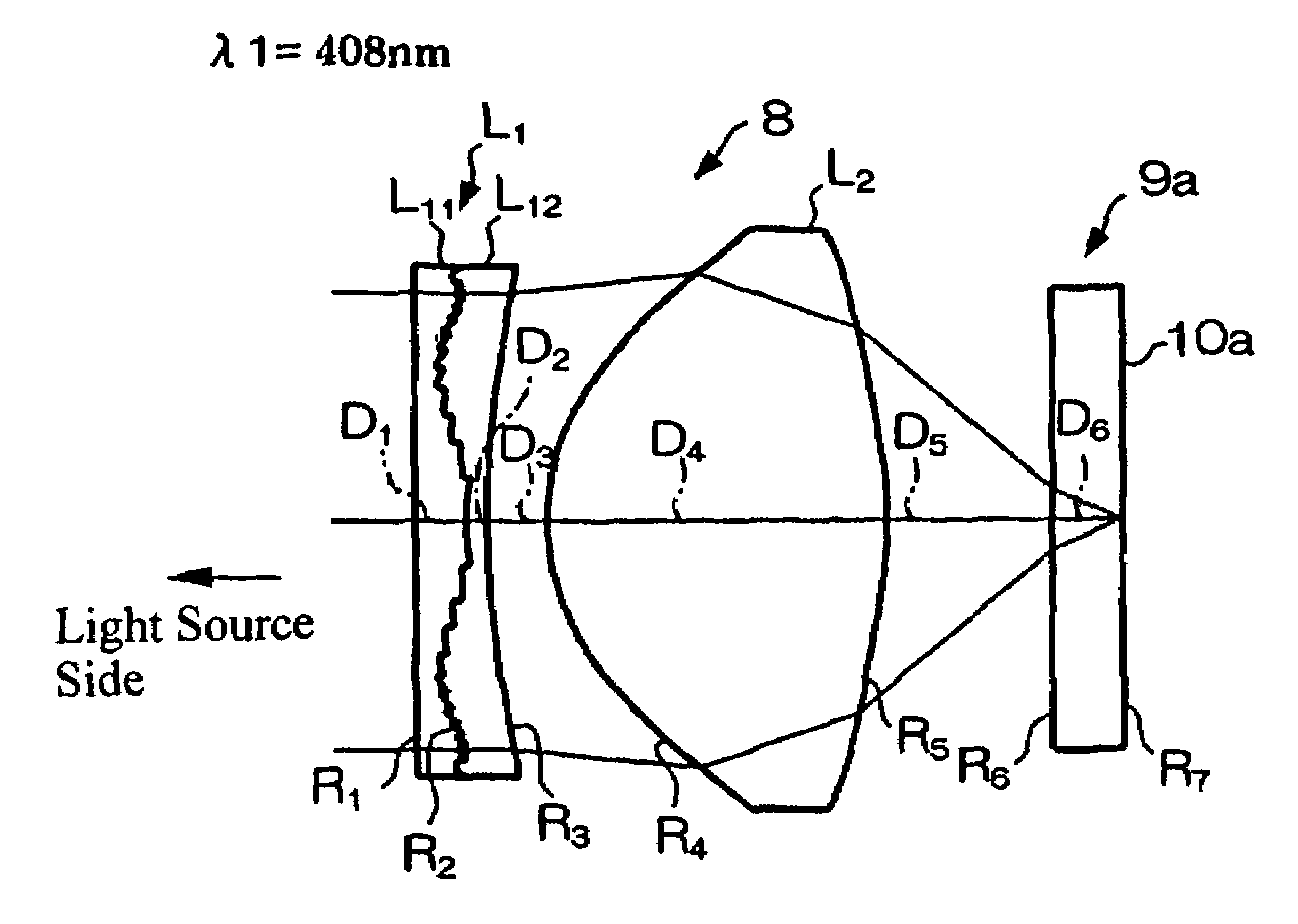
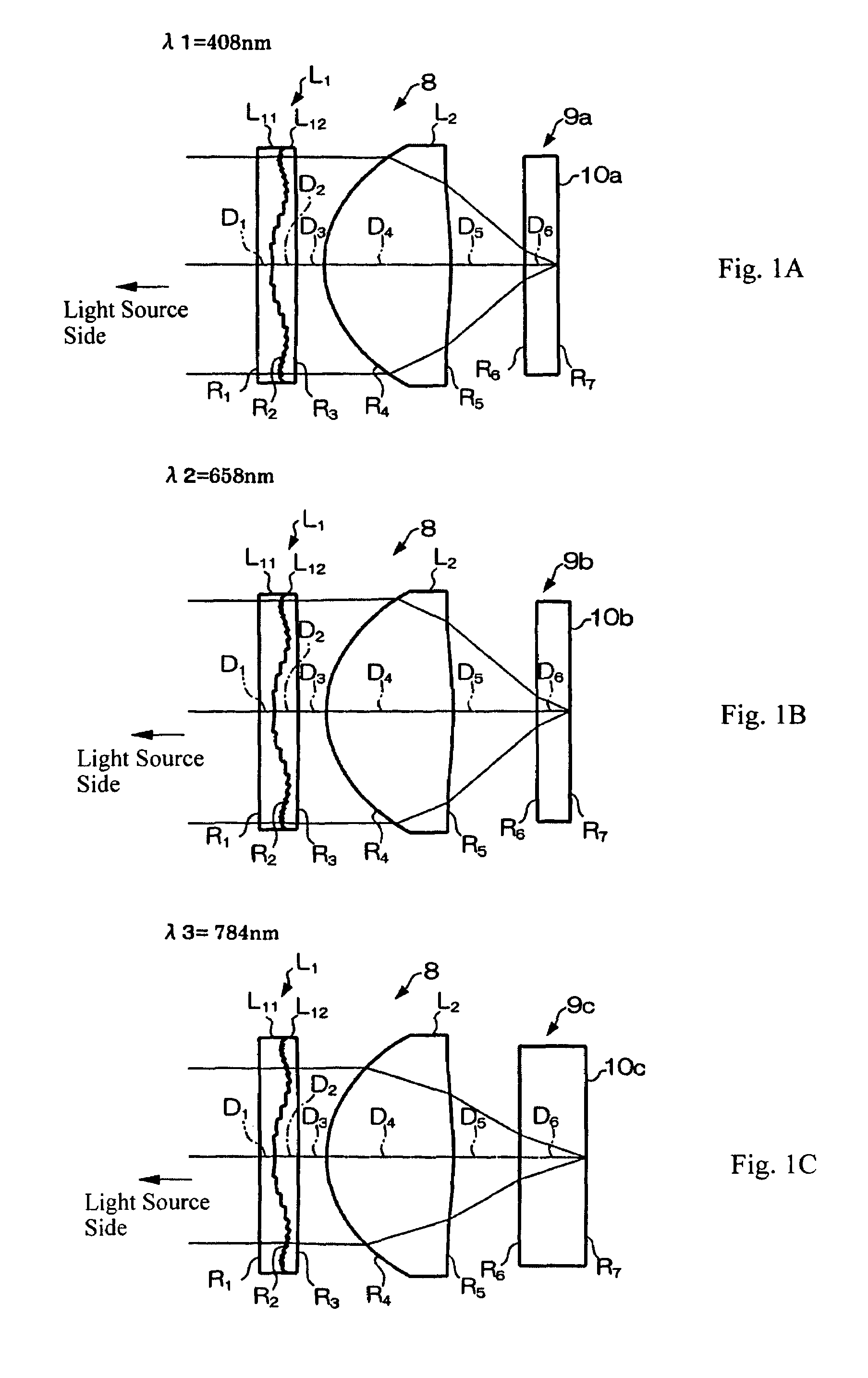
[0078]As described previously, FIGS. 1A-1C are schematic diagrams that depict cross-sectional views of the objective optical system according to Embodiment 1 of the present invention, with FIG. 1A showing the operation of the objective optical system when used with a first optical recording medium 9a, with FIG. 1B showing the operation of the objective optical system when used with a second optical recording medium 9b, and with FIG. 1C showing the operation of the objective optical system when used with a third optical recording medium 9c. Additionally, as described previously, FIG. 5 is a schematic diagram of an optical pickup device using the objective optical system according to Embodiment 1 of FIGS. 1A-1C.

[0079]As shown in FIGS. 1A-1C, the objective optical system 8 includes, arranged in order along an optical axis from a light source side, a diffractive optical element L1 and an objective lens L2. The diffractive optical element L1 is a cemented structure of two lens elements L...

embodiment 2

[0093]As described previously, FIGS. 3A-3C are schematic diagrams that depict cross-sectional views of the objective optical system according to Embodiment 2 of the present invention, with FIG. 3A showing the operation of the objective optical system when used with a first optical recording medium 9a, with FIG. 3B showing the operation of the objective optical system when used with a second optical recording medium 9b, and with FIG. 3C showing the operation of the objective optical system when used with a third optical recording medium 9c. The objective optical system 8 of FIGS. 3A-3C according to Embodiment 2 is similar to that of FIGS. 1A-1C according to Embodiment 1. However, in addition to Embodiment 2 including aspheric surfaces for surfaces that are aspheric surfaces in Embodiment 1, in Embodiment 2, the surface of the diffractive optical element L1 at the optical recording medium side is also an aspheric surface. Also, in Embodiment 2, non-zero aspheric coefficients up to A10...


PUM


Abstract

An objective optical system includes a diffractive optical element on the light source side of an objective lens for focusing incident light of three different wavelengths with two different numerical apertures onto three different optical recording media. The diffractive optical element is formed of two lens elements made of different materials that are cemented together at a diffractive surface. Three conditions are satisfied so as to achieve optimum imaging. The diffractive surface may be shaped so that the order of the diffracted light of the shortest wavelength λ2 having the largest diffracted intensity is different from the order of the diffracted light of the second wavelength λ2 having the largest diffracted intensity, and the order of the diffracted light of the first wavelength λ1 having the largest diffracted intensity is also different from the order of the diffracted light of the third wavelength λ3 having the largest diffracted intensity.

Description

FIELD OF THE INVENTION[0001]The present invention relates to an objective optical system that includes a diffractive optical element and an optical pickup device that uses such an objective optical system for recording or reproducing information with one of three different light beams of different wavelengths. Each beam of light is efficiently focused on a corresponding one of three different types of optical recording media with different technical standards, including different numerical apertures of the objective optical system for each of the three different wavelengths used and different substrate thicknesses of the different optical recording media. The diffractive optical element includes a diffractive surface that diffracts the light of three different wavelengths differently so that the diffracted light beam of each wavelength is efficiently focused at a desired distance along the optical axis of the objective optical system where a recording region of the corresponding rec...

Claims


Application Information

Patent Timeline
Patent Type & Authority Patents(United States)
IPC IPC(8): G11B7/00G02B13/00G02B5/18G02B13/18G11B7/135G11B7/1367G11B7/1372G11B7/1374G11B7/1392
CPCG11B7/1367G11B7/1374G11B7/13922G11B2007/0006G11B2007/13727
Inventor KITAHARA, YUORI, TETSUYAKATSUMA, TOSHIAKIMORI, MASAOYAMAKAWA, HIROMITSU
Owner FUJI PHOTO OPTICAL CO LTD
Why Eureka
Try Eureka