Method of constructing a concrete shear core multistory building

a multi-story building and concrete technology, applied in special buildings, building repairs, parkings, etc., can solve the problems of affecting the functional and aesthetic aspects of the building, the construction of a conventional concrete core is relatively time-consuming and has a significant impact on the total time required to complete the building, and achieves the effect of quick erection and enhancing the structural integrity of the building

Inactive Publication Date: 2008-11-04
W LEASE LEWIS
View PDF13 Cites 35 Cited by
  • Summary
  • Abstract
  • Description
  • Claims
  • Application Information

AI Technical Summary

Benefits of technology

[0012]An improved method for building concrete shear core buildings is disclosed that retains the well-known benefits of shear core buildings while overcoming many of the disadvantages, including permitting the concrete shear core to be completed at a pace similar to the pace of constructing the steel framing and floors. The method utilizes a steel erection structure that may be quickly erected and is sized to support multiple floors of the building cooperatively with the steel framing structure. The steel erection structure includes the steel reinforcing bar for the concrete shear core. The floors may be built up—for example, 7 to 9 floors up—before beginning pouring the concrete shear core, and then may be erected at a rapid pace due to the reinforcing bar being already in place, and the steel floors and related structure completed ahead of the concrete core. The steel framing and floors and the concrete shear core, may then proceed at a similar pace, to complete the building. If the concrete shear core is designed to support the building upon completion, without accounting for the additional structural support provided by the steel erection structure, then the steel erection structure provides redundant reinforcing, enhancing the structural integrity of the building.
[0014]In a preferred embodiment, the vertical columns of the steel erection subassembly are disposed between the forms, such that these columns are also substantially embedded in the concrete. The beams may be positioned adjacent the outer forms, such that the concrete flows into the volume defined in the inner side of the beams, thereby further locking the beams into place.

Problems solved by technology

For example, in a concrete shear core building, no structural steel bracing or moment connections are required, which are expensive and may interfere with functional and aesthetic aspects of the building.
There are disadvantages to conventional concrete shear core construction, however.
In particular, the construction of a conventional concrete core is relatively time-consuming and has a significant impact on the total time required to complete a building.
Staging the steel erection work requires mobilization and demobilization of the steel-working equipment and work force, thereby further increasing the cost of construction.
Other disadvantages to conventional concrete shear core construction are that it typically requires rebuilding the core forms at story height transitions or using expensive self-climbing forms, and requires redundant construction equipment, such as temporary stair towers and hoists.
The concrete shear core construction, therefore, is typically a pacing task, directly impacting the time required for constructing taller buildings.

Method used


Image

  • Method of constructing a concrete shear core multistory building
  • Method of constructing a concrete shear core multistory building
  • Method of constructing a concrete shear core multistory building

Examples


Embodiment Construction

[0024]As discussed in detail below, the present invention is directed to a method for constructing concrete shear core buildings, wherein a central steel erection structure is provided that is adapted to support at least a portion of the peripheral steel structure and floors, such that the structural steel and floor construction may proceed ahead of the concrete shear core. The steel erection structure simplifies the building of the concrete shear core, as discussed in detail below, enabling the construction of the concrete shear core to proceed at a pace similar to the structural steel construction, thereby reducing the time required to erect medium- and high-rise concrete shear core structures.

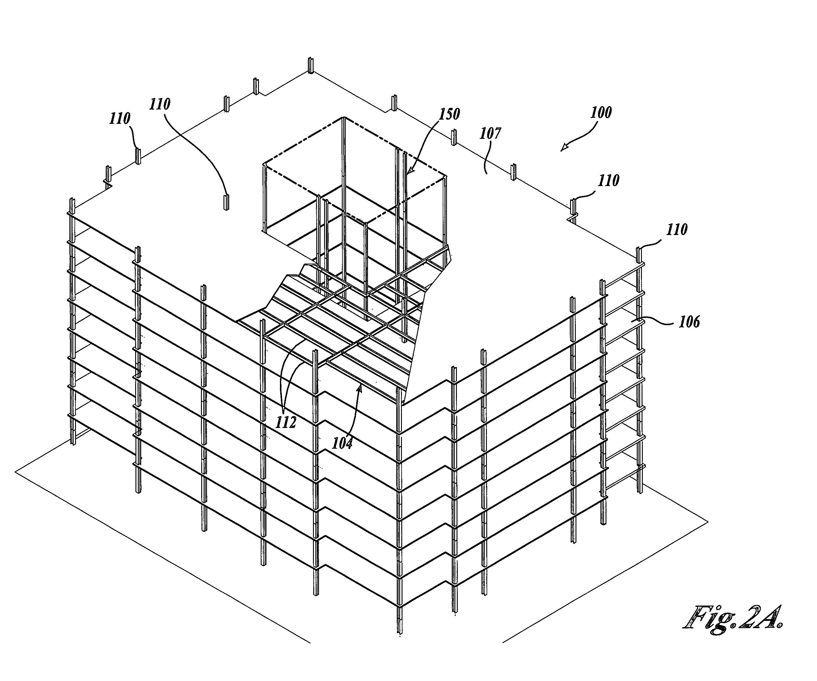
[0025]FIG. 2A shows a portion of a steel reinforced concrete shear core building 100 at an intermediate stage of construction and being built according to the teachings of the present invention. At the stage of construction shown in FIG. 2A, approximately nine floors of steel framing 104 and...


PUM

PropertyMeasurementUnit
heightaaaaaaaaaa
lengthaaaaaaaaaa
volumeaaaaaaaaaa

Abstract

Method for constructing concrete shear core buildings wherein a steel erection structure is built having steel columns and beams. The steel erection structure is made from pre-assembled segments that include the steel reinforcing bar for the concrete shear core. A peripheral steel structure is also constructed and the steel floors are built, cooperatively supported by the steel erection structure and the peripheral structure. Forms are positioned generally about the steel reinforcing bars and at least a portion of the steel erection structure. Concrete is poured in the volume defined by the forms, to build a portion of the concrete shear core. In a preferred embodiment, the steel erection structure and peripheral steel structure proceed approximately seven to nine floors ahead of the concrete shear core, and the concrete shear core is sized to support the completed building without accounting for the additional structural support provided by the steel erection structure.

Description

FIELD OF THE INVENTION[0001]The present invention is in the field of building construction methods and, in particular, to methods for constructing mid- and high-rise buildings.BACKGROUND OF THE INVENTION[0002]The construction of mid- to high-rise building structures has progressed dramatically over the past decades, with advances in materials, techniques, and analytical methods that enable the economical construction of structurally sound multistory buildings. High-rise structures have many advantages, particularly in an urban setting, including, for example, more productive use of limited land space, economies of scale for building owners and managers, relatively low construction costs per square foot of usable space, attractive and desirable living and / or working space for users, and reduction in urban sprawl for municipalities.[0003]A construction method of choice, particularly in structures more than a few stories tall, utilizes a concrete shear core that functions as a primary ...

Claims


Application Information

Patent Timeline
Patent Type & Authority Patents(United States)
IPC IPC(8): E04B1/00E04B1/16E04B1/34E04B1/35E04G21/00
CPCE04B1/3404E04B1/3505
Inventor RAFTERY, MICHAEL CHRISTOPHERGARLAND, MARK RUSSELL
Owner W LEASE LEWIS
Why Eureka
Try Eureka