Method and system for rich-lean catalytic combustion

a catalytic combustion and fuel technology, applied in the combustion of catalytic materials, combustion types, turbine/propulsion engine ignition, etc., can solve the problems of catalyst bed overheating, catalyst will not be operational at part power conditions, and use of lean-burning catalytic systems in advanced cycle engines that require high firing temperatures (over 2200° f.) limited

Inactive Publication Date: 2008-11-04
UNITED TECH CORP
View PDF26 Cites 10 Cited by
  • Summary
  • Abstract
  • Description
  • Claims
  • Application Information

AI Technical Summary

Problems solved by technology

However, such systems require preheating as the catalyst will not light at all combustor inlet temperatures.
But even for these systems, the catalyst will not be operational at part power conditions.
Furthermore, the use of lean-burn catalytic systems in advanced cycle engines that require high firing temperatures (above 2200° F.) is limited.
In such cases, high flame speeds and temperatures lead to overheating of the catalyst bed and reduced product life.
However, the products of the fuel-rich reaction system must then be burned in a more conventional homogeneous environment, i.e., normal combustion, which produces NOx emissions.
Variation in combustor hardware, construction, location, and ambient conditions suggest that the 3 ppm emissions may not be attainable easily for the next generation of burners.

Method used


Image

  • Method and system for rich-lean catalytic combustion
  • Method and system for rich-lean catalytic combustion
  • Method and system for rich-lean catalytic combustion

Examples


Embodiment Construction

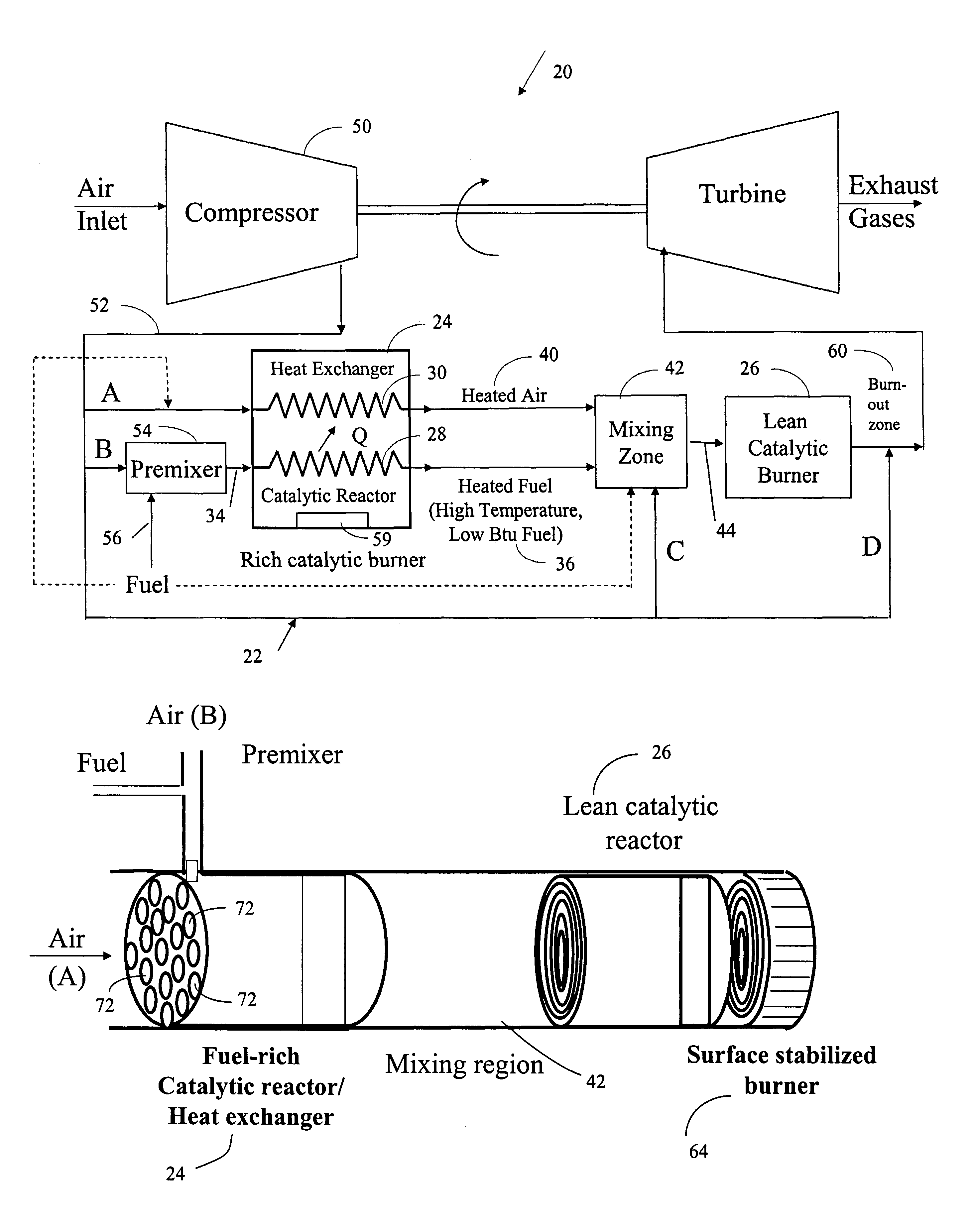
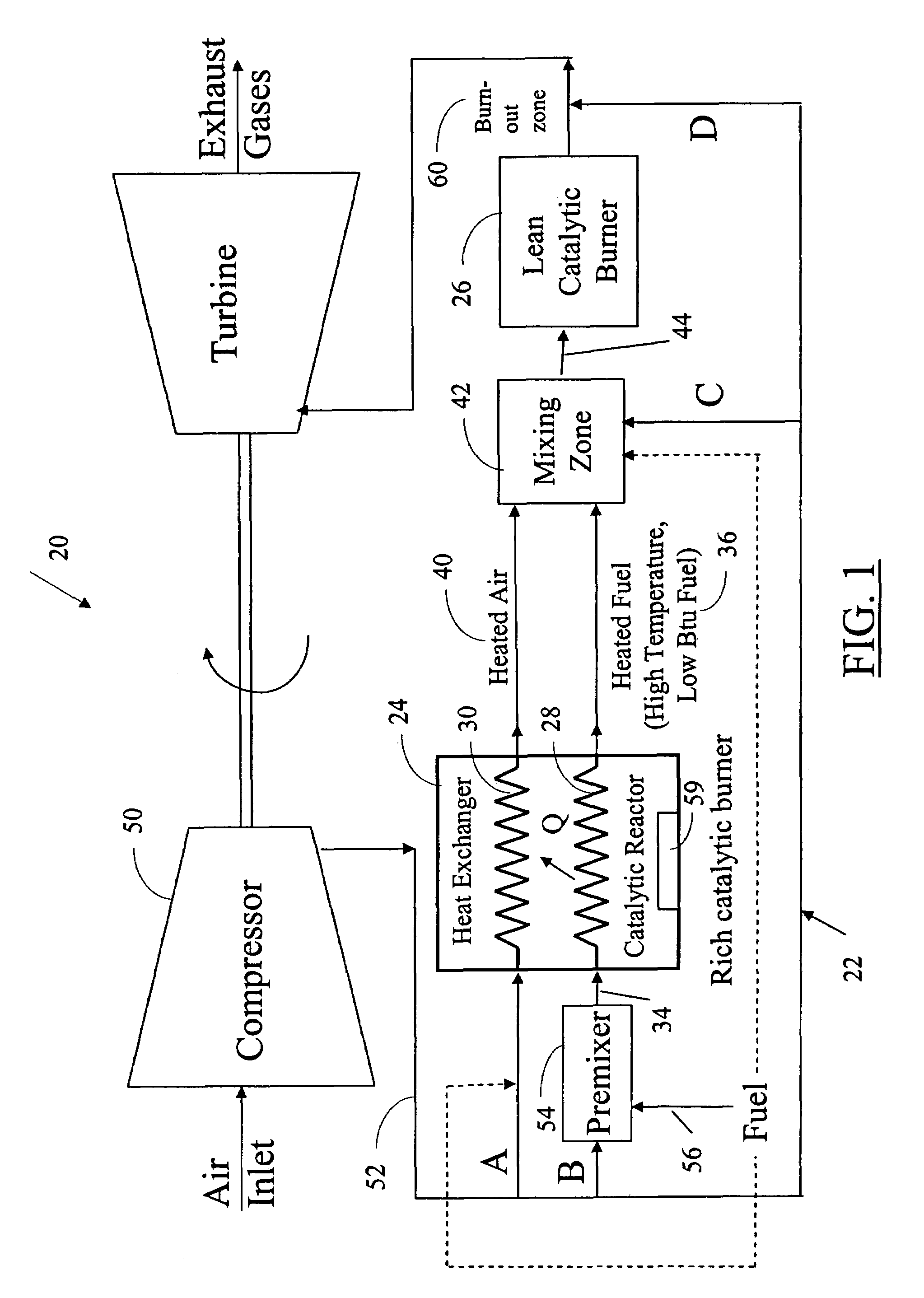
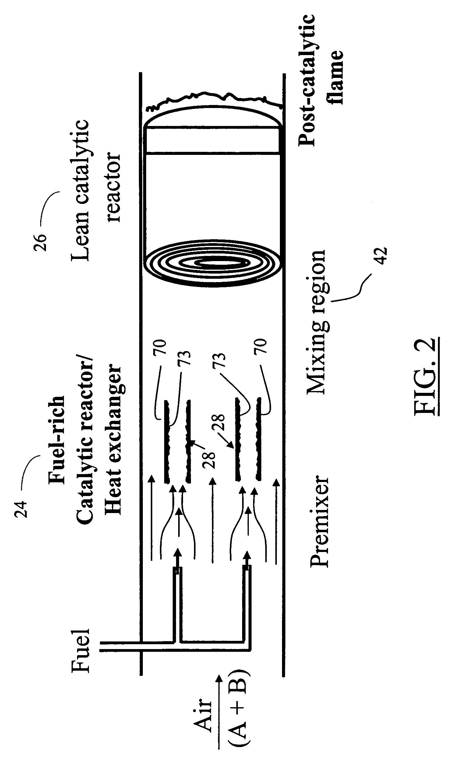
[0016]Referring to the FIG. 1, a gas turbine engine 20 using a rich-lean catalytic combustion system 22 constructed in accordance with the teachings of the present disclosure is schematically shown. The combustion system 22 includes a rich catalytic burner 24 and a lean catalytic burner 26. The rich catalytic burner 24 includes a rich catalytic reactor 28 and a heat exchanger 30. The rich catalytic reactor 28 burns a fuel rich mixture 34 to provide heated fuel 36. The heat exchanger 30 receives an air stream A that absorbs the heat from the catalytic burning of the fuel rich mixture 34 to keep the reaction in the rich catalytic reactor 28 at or below a catalytic reaction threshold temperature. Resulting heated air 40 from the heat exchanger 30 and the heated fuel 36 are mixed in a mixing zone 42 to provide a heated fuel-air mixture 44. The lean catalytic burner 26 receives and burns the heated fuel-air mixture 44. The combination of the rich catalytic burner 24 in front of the lean ...


PUM


Abstract

A gas turbine engine using a rich-lean catalytic combustion system includes a rich catalytic burner and a lean catalytic burner. The rich catalytic burner includes a rich catalytic reactor and a heat exchanger. The rich catalytic reactor catalytically burns a fuel rich mixture to provide a heated fuel. The heat exchanger receives a stream of air that absorbs a portion of the heat from the catalytic burning of the fuel rich mixture to keep the reaction in the rich catalytic reactor at or below a threshold temperature. A resulting heated air from the heat exchanger and the heated fuel are mixed in a mixing zone to provide a heated fuel-air mixture. The lean catalytic burner receives and burns the heated fuel-air mixture.

Description

FIELD OF THE DISCLOSURE[0001]The present disclosure generally relates to methods and systems for combustion of hydrocarbon fuels, and more particularly, to a method and system for rich-lean catalytic combustion of hydrocarbon fuels.BACKGROUND OF THE DISCLOSURE[0002]Gas turbines must comply with ever increasing regulatory emissions standards while maintaining or optimizing performance and cost. Mandated emissions regulations to reduce oxides of nitrogen (NOx) are the main driving force behind the development of new and costly technologies involving premixed combustion, catalytic systems, and post combustion clean-up. To comply with emission standards, lean-burning catalytic systems have advanced significantly to provide a stable (dynamic-free) burn with low NOx emissions. However, such systems require preheating as the catalyst will not light at all combustor inlet temperatures. In aeroderivative and advanced cycle engines, the temperature of the combustor inlet at full power conditi...

Claims


Application Information

Patent Timeline
Patent Type & Authority Patents(United States)
IPC IPC(8): F02C7/22F02C7/26
CPCF23C6/045F23C13/00F23L15/04F23R3/40Y02E20/34
Inventor COLKET, III, MEREDITH B.
Owner UNITED TECH CORP
Why Eureka
Try Eureka