

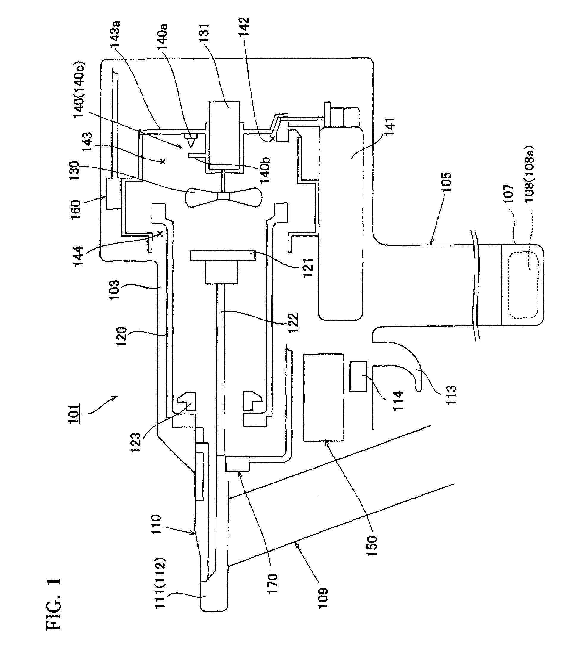
Combustion power tool
a technology of combustion power and power tools, which is applied in the direction of manufacturing tools, nailing tools, machines/engines, etc., can solve the problems of inability to perform subsequent sparking and inability to achieve ignition, and achieve the effect of reliable ignition, and reducing the number of ignition circuits
- Summary
- Abstract
- Description
- Claims
- Application Information
AI Technical Summary
Benefits of technology
Problems solved by technology
Method used
Image

Examples
first embodiment
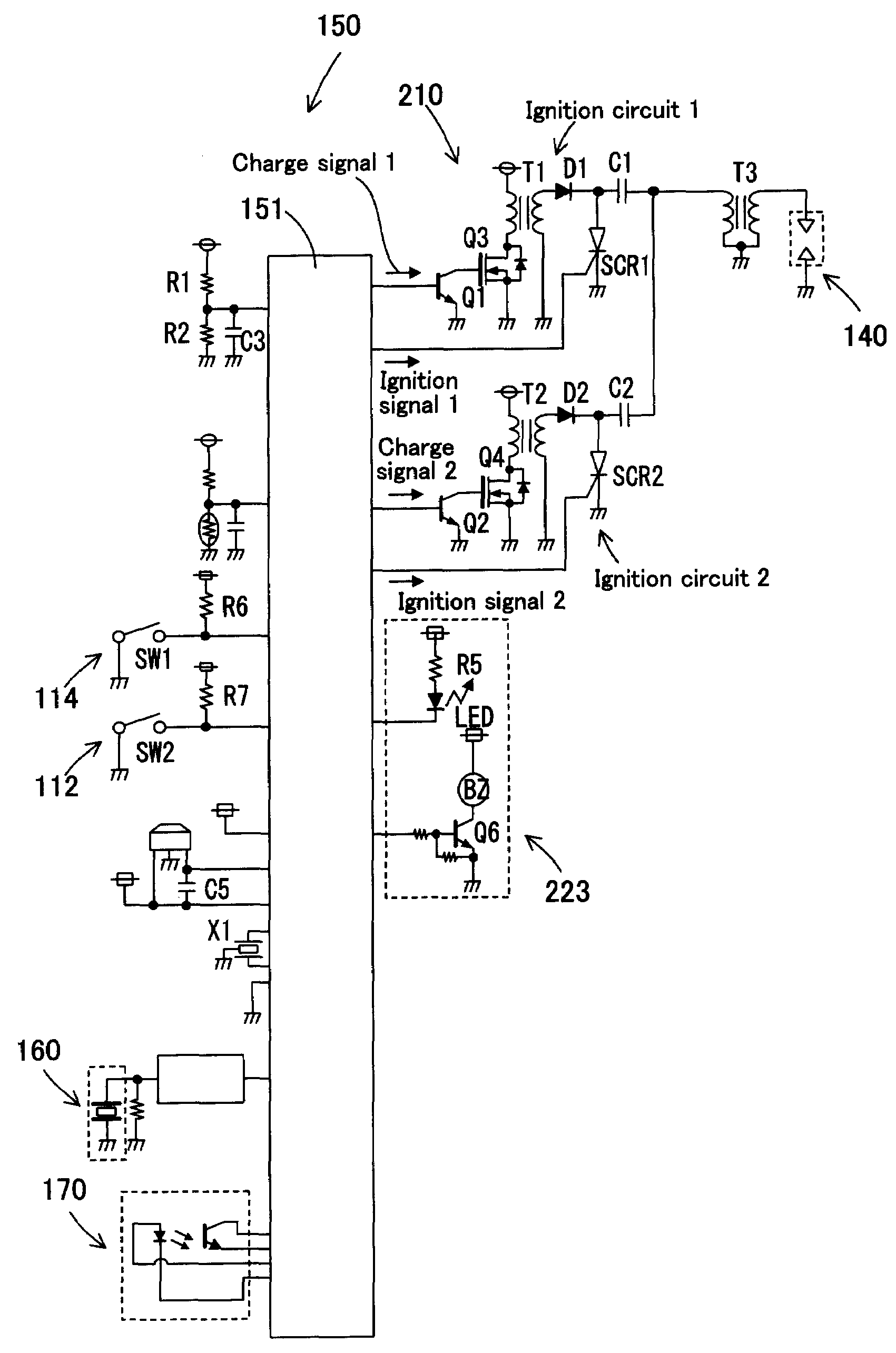
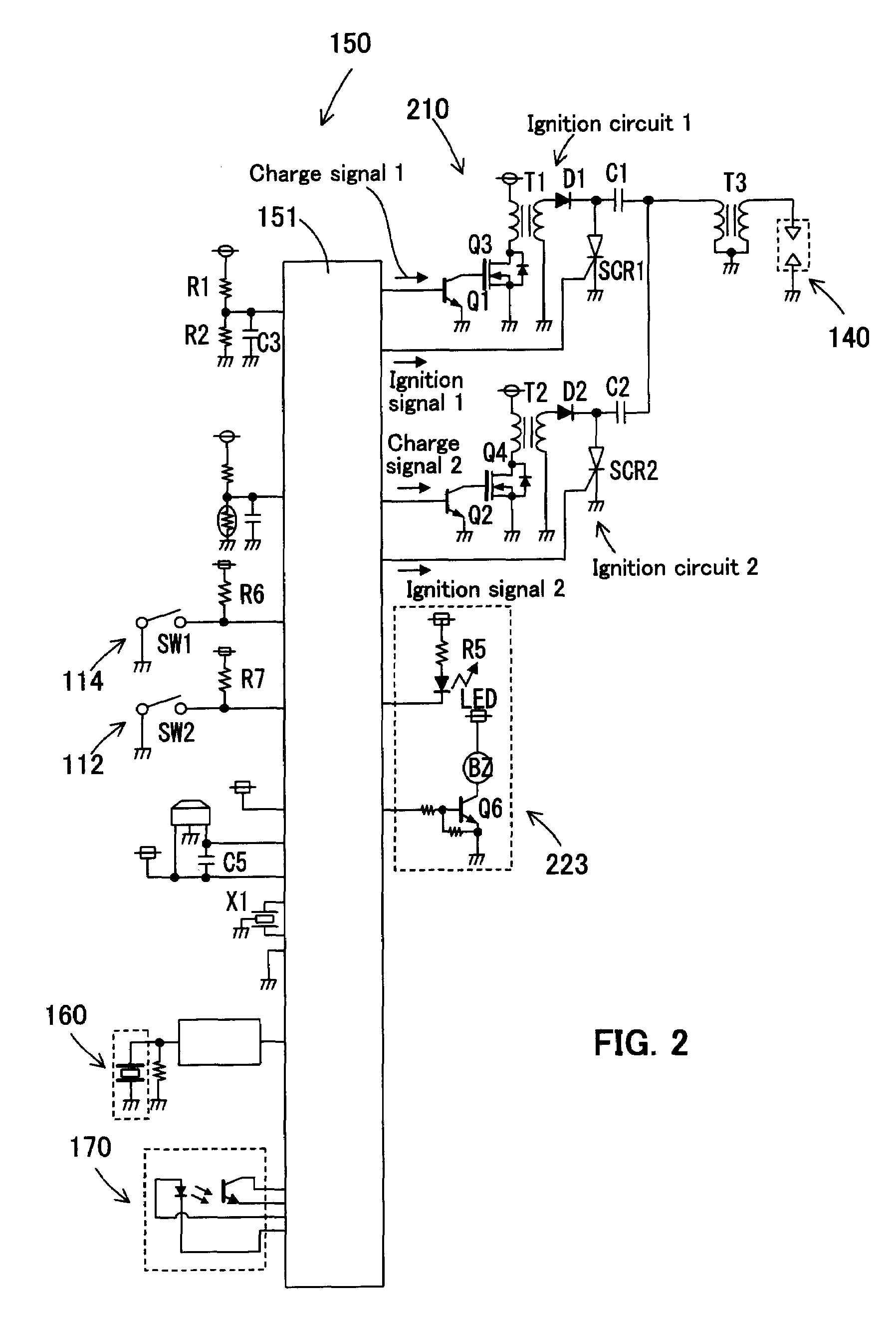
[0051]FIG. 2 is a schematic diagram showing the ignition circuit unit 210 in the ignition control device 150 of the present embodiment. As shown in FIG. 2, the ignition circuit unit 210 is featured by the construction having a combination of the “capacitor-type” ignition circuits 1, 2. Specifically, the ignition circuit unit 210 includes the charging capacitors C1, C2 and trigger elements SCR1, SCR2 for discharging the charging capacitors C1, C2, on the primary side of the ignition coil. The capacitor-type ignition circuits 1, 2 are features that correspond to the “plurality of ignition circuits” according to this invention. Charge in the charging capacitor C1 of the ignition circuit 1 is executed based on a charge signal 1 from the microcomputer 151 and discharge in the charged charging capacitor C1 is executed based on an ignition signal 1 from the microcomputer 151. Likewise, charge in the charging capacitor C2 of the ignition circuit 2 is executed based on a charge signal 2 from...
second embodiment
[0054]FIG. 3 is a schematic diagram showing the ignition circuit unit 220 in the ignition control device 150 of the present embodiment. As shown in FIG. 3, like the ignition circuit unit 210, the ignition circuit unit 220 has a construction having a combination of the “capacitor type” ignition circuits 1, 2 and further includes current detecting circuits 221, 222.
[0055]The current detecting circuit 221 is disposed in parallel with the charging capacitors C1, C2 and serves to continuously or intermittently detect a spark current and compare the detected current value with a previously stored current value each time, thereby detecting any abnormal condition of the charging capacitors C1, C2. The current detecting circuit 221 is disposed on the ignition coil and serves to detect a short circuit of the ignition coil. The charging capacitors C1, C2 form the “current detecting section for detecting spark current at the time of plug ignition of the single spark plug” according to this inve...
PUM
 Abstract
Description
Claims
Application Information