Gas sensor and nitrogen oxide sensor

a technology which is applied in the field of gas sensor and nitrogen oxide sensor, can solve the problems of inability to perform the measurement of a combustion gas produced under such a combustion condition, the influence of noise of conventional sensors, and the suffering of the above-mentioned sensors, so as to improve the measurement accuracy

Inactive Publication Date: 2008-11-04
NGK INSULATORS LTD
View PDF40 Cites 8 Cited by
  • Summary
  • Abstract
  • Description
  • Claims
  • Application Information

AI Technical Summary

Benefits of technology

[0014]The present invention has been made taking such problems into consideration, an object of which is to provide a gas sensor and a nitrogen oxide sensor which make it possible to avoid the influence of the pulsation of the exhaust gas pressure generated in the measurement gas, and improve the measurement accuracy obtained on the detecting electrode.
[0019]In this arrangement, the pulsation (=dynamic pressure) of the exhaust gas pressure is attenuated by the wall resistance of the diffusion rate-determining means. Specifically, the attenuation is effected up to the level at which the ratio between the dynamic pressure and the static pressure (dynamic pressure / static pressure) is not more than 25%. Therefore, it is possible to effectively suppress the shift-up phenomenon of the sensor output which would be otherwise caused by the fluctuation of the dynamic pressure.
[0022]As a result, the correlation is improved between the oxygen-pumping amount effected by the pumping means in the processing space and the oxygen concentration in the measurement gas. It is possible to improve the measurement accuracy obtained on the measuring pumping means or the concentration-detecting means. Simultaneously, for example, it is possible to concurrently use the internal space as a sensor for determining the air-fuel ratio.
[0024]In this arrangement, the gas sensor is prevented from clogging of particles (for example, soot and oil combustion waste) produced in the measurement gas in the external space, which would be otherwise caused in the vicinity of the inlet of the buffering space. Thus, it is possible to measure the predetermined gas component more accurately. Further, it is possible to maintain a highly accurate state over a long period of time.
[0029]According to the present invention, the pulsation (=dynamic pressure) of the exhaust gas pressure is attenuated by the wall resistance of the diffusion rate-determining means. Specifically, the attenuation is effected up to the level at which the ratio between the dynamic pressure and the static pressure (dynamic pressure / static pressure) is not more than 25%. Therefore, it is possible to effectively suppress the shift-up phenomenon of the sensor output which would be otherwise caused by the fluctuation of the dynamic pressure.
[0031]Also in this aspect, the pulsation (=dynamic pressure) of the exhaust gas pressure is attenuated by the wall resistance of the diffusion rate-determining means. Specifically, the attenuation is effected up to the level at which the ratio between the dynamic pressure and the static pressure (dynamic pressure / static pressure) is not more than 25%. Therefore, it is possible to effectively suppress the shift-up phenomenon of the sensor output which would be otherwise caused by the fluctuation of the dynamic pressure.

Problems solved by technology

However, the sensor as described above suffers the following problems.
For this reason, the conventional sensor tends to suffer influence of noise.
Therefore, the conventional sensor has a drawback in that it is impossible to perform the measurement for a combustion gas produced under such a combustion condition.
Therefore, when the dynamic pressure is increased, it is inevitable to suffer any deterioration of the correlation between the oxygen-pumping amount effected by the main pump in the first space and the oxygen concentration in the measurement gas.
It is feared that the disturbance of the oxygen concentration caused in the first space may bring about any deterioration concerning the control of the oxygen concentration in the second space communicating with the first space and the accuracy of measurement effected by the detecting electrode as the NOx-detecting section.

Method used


Image

  • Gas sensor and nitrogen oxide sensor
  • Gas sensor and nitrogen oxide sensor
  • Gas sensor and nitrogen oxide sensor

Examples


first embodiment

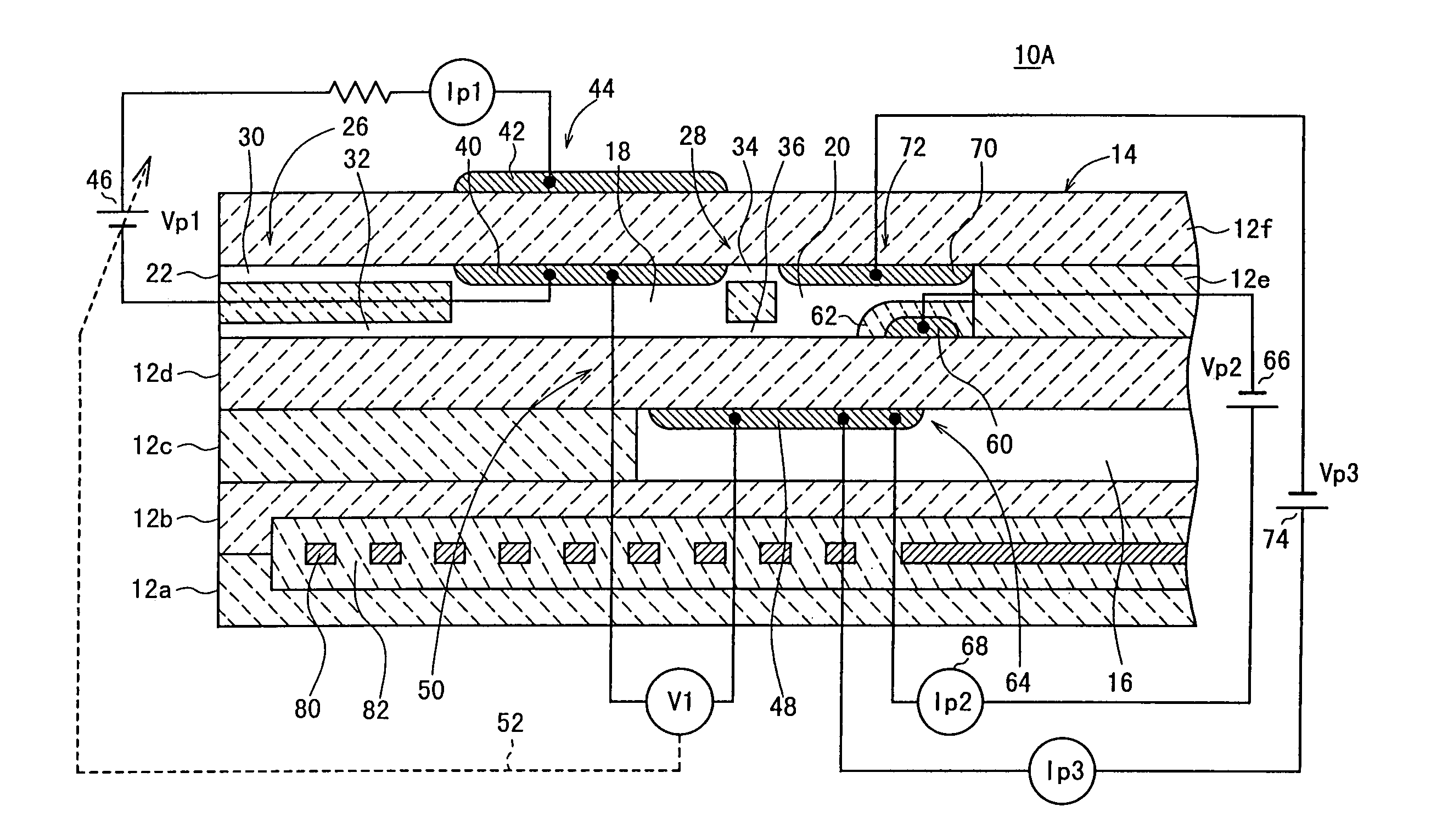
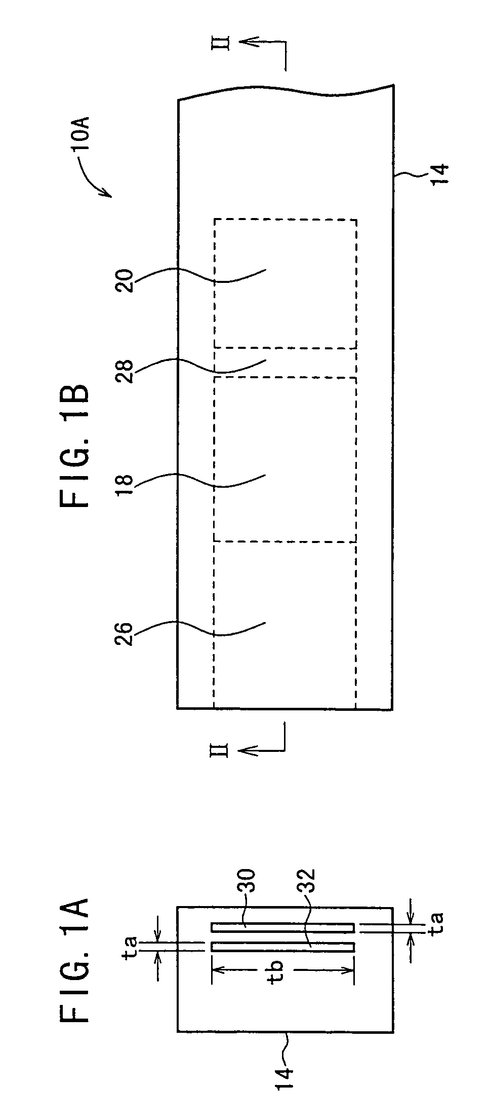
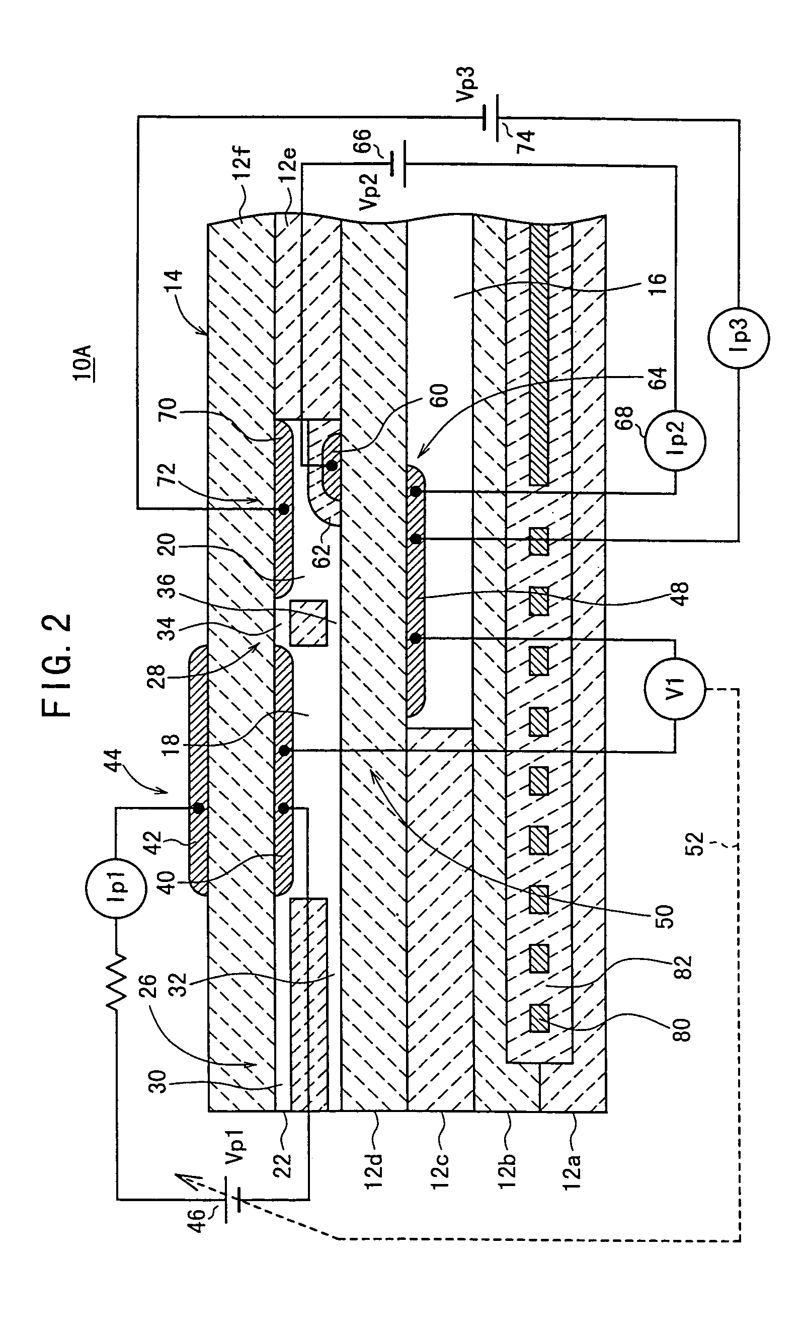
[0082]As shown in FIGS. 1A, 1B, and 2, a gas sensor 10A includes a sensor element 14 provided with a substrate comprising, for example, six stacked solid electrolyte layers 12a to 12f composed of ceramics based on the use of oxygen ion-conductive solid electrolytes such as ZrO2.

[0083]In the sensor element 14, first and second layers from the bottom are designated as first and second substrate layers 12a, 12b respectively. Third and fifth layers from the bottom are designated as first and second spacer layers 12c, 12e respectively. Fourth and sixth layers from the bottom are designated as first and second solid electrolyte layers 12d, 12f respectively.

[0084]A space 16 (reference gas-introducing space 16), into which a reference gas such as atmospheric air to be used as a reference for measuring oxides is introduced, is formed between the second substrate layer 12b and the first solid electrolyte layer 12d, the space 16 being comparted by a lower surface of the first solid electrolyt...

first modified embodiment

[0134]At first, as shown in FIGS. 13A, 13B, and 14, a gas sensor 10Aa differs in that the first and second diffusion rate-determining sections 26, 28 are formed by single laterally extending slits 110, 112 respectively.

[0135]Specifically, the first diffusion rate-determining section 26 includes the slit 110 having a laterally extending aperture formed at a front end portion of the second spacer layer 12e to make contact with the upper surface of the first solid electrolyte layer 12d, the aperture being formed to extend with an identical aperture width up to the first chamber 18. The second diffusion rate-determining section 28 includes the slit 112 having an aperture formed at a terminal end portion of the first chamber 18 of the second spacer layer 12e to make contact with the upper surface of the first solid electrolyte layer 12d, the aperture being formed to extend with an identical aperture width up to the second chamber 20. In the first modified embodiment, each of the slits 1...

second modified embodiment

[0136]Next, as shown in FIGS. 15A, 15B, and 16, a gas sensor 10Ab differs in that the first and second diffusion rate-determining sections 26, 28 are formed by single laterally extending wedge-shaped slits 114, 116 respectively.

[0137]Specifically, the first diffusion rate-determining section 26 includes the wedge-shaped slit 114 having a laterally extending aperture formed at a front end portion of the second spacer layer 12e to make contact with the upper surface of the first solid electrolyte layer 12d, the aperture being formed to extend with an aperture width (width in the vertical direction) gradually enlarged toward the first chamber 18. The second diffusion rate-determining section 28 includes the wedge-shaped slit 116 having a laterally extending aperture formed at a terminal end portion of the first chamber 18 of the second spacer layer 12e to make contact with the upper surface of the first solid electrolyte layer 12d, the aperture being formed to extend with an aperture ...


PUM

PropertyMeasurementUnit
length tbaaaaaaaaaa
length tbaaaaaaaaaa
partial pressureaaaaaaaaaa

Abstract

A gas sensor for measuring an amount of a measurement gas component, including a solid electrolyte having an internal space, a gas-introducing port for introducing measurement gas from an external space into the internal space, diffusion rate-determining means between the internal space and the gas-introducing port, and inner and outer pumping electrodes for pumping-processing oxygen contained in the measurement gas. The diffusion rate-determining means includes slits each having, when viewed in a plane substantially perpendicular to a longitudinal extension axis thereof, two dimensions, with at least one dimension of each slit being not more than 10 microns.

Description

CROSS REFERENCE TO RELATED APPLICATIONS[0001]This application is a continuation of U.S. application Ser. No. 10 / 342,846, filed Jan. 15, 2003, now U.S. Patent No. 6,770,181,which is a continuation of U.S. application Ser. No. 10 / 021,196, filed Oct. 30, 2001, now U.S. Pat. No. 6,527,929, which is a continuation of U.S. application Ser. No. 09 / 348,857, filed Jul. 7, 1999, now U.S. Patent No. 6,355,152, the entireties of which are incorporated herein by reference.BACKGROUND OF THE INVENTION[0002]1. Field of the Invention[0003]The present invention relates to a gas sensor and a nitrogen oxide sensor for measuring oxides such as O2, NO, NO2, SO2, CO2, and H2O contained in, for example, atmospheric air and exhaust gas discharged from vehicles or automobiles, and inflammable gases such as CO and CnHm.[0004]2. Description of the Related Art[0005]Those hitherto known as the method for measuring NOx in a measurement gas such as combustion gas include a technique in which the NOx-reducing abili...

Claims


Application Information

Patent Timeline
Patent Type & Authority Patents(United States)
IPC IPC(8): G01N27/407G01N27/419G01N27/416G01N27/417
CPCG01N27/4072G01N27/417G01N27/419
Inventor KATO, NOBUHIDENAKAGAKI, KUNIHIKO
Owner NGK INSULATORS LTD
Why Eureka
Try Eureka