Defect inspection method and defect inspection system using the method

a defect inspection and defect technology, applied in the direction of dividing poultry, instruments, image enhancement, etc., can solve the problems of surface irregularities or color defects, and color defects, and achieve high precision and efficient detection

Inactive Publication Date: 2008-11-04
ORMON CORP
View PDF17 Cites 9 Cited by
  • Summary
  • Abstract
  • Description
  • Claims
  • Application Information

AI Technical Summary

Benefits of technology

[0022]Meanwhile, according to the present invention, since the different color is used in the illumination and each image data reflects the reflected light of either one of the illuminations, the intensity of each illumination can be adjusted so as to be suitable for the detection of each defect. Thus, both irregular defect and color defect can be detected with high precision.
[0038]According to the present invention, with only one imaging operation, an image suitable for detecting both irregular defect and the color defect on the surface of the object can be generated and each defect can be detected with high precision. Furthermore, since the image is taken only one time, even when many objects are sequentially to be inspected, very efficient detection can be implemented.

Problems solved by technology

Although a surface of such product is made of a colored resin or metal, the surface could have an irregular defect or a color defect.
The irregular defect is generated when the surface is protruded or recessed caused by a manufacturing defect.
The irregular defect includes a scratch generated after manufactured.
The color defect is generated when a peripheral coating material is attached on the surface at the time of manufacturing.
In addition, an irregular defect on the surface of the work is detected using the image generated by the first imaging device, and a color defect on the surface of the work is detected using the image generated by the second imaging device.
However, according to the method in Japanese Unexamined Patent Publication No. 2003-75363, since the two imaging devices are provided, the cost becomes high.
In addition, they occupy a large space in an optical system, and control for the imaging devices individually is complicated.
According to this method, a processing time is long, so that many works cannot be processed efficiently.

Method used


Image

  • Defect inspection method and defect inspection system using the method
  • Defect inspection method and defect inspection system using the method
  • Defect inspection method and defect inspection system using the method

Examples


Embodiment Construction

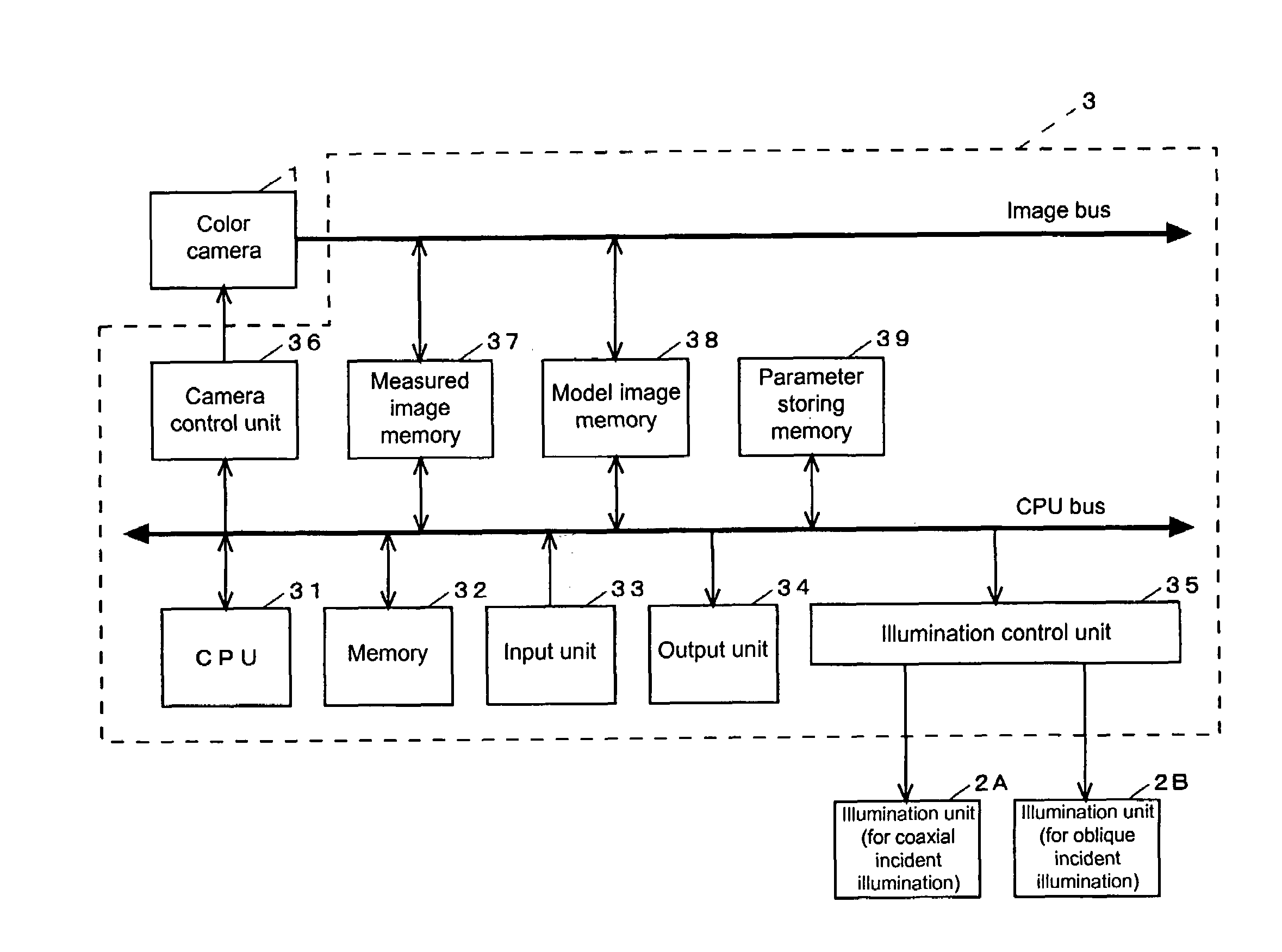
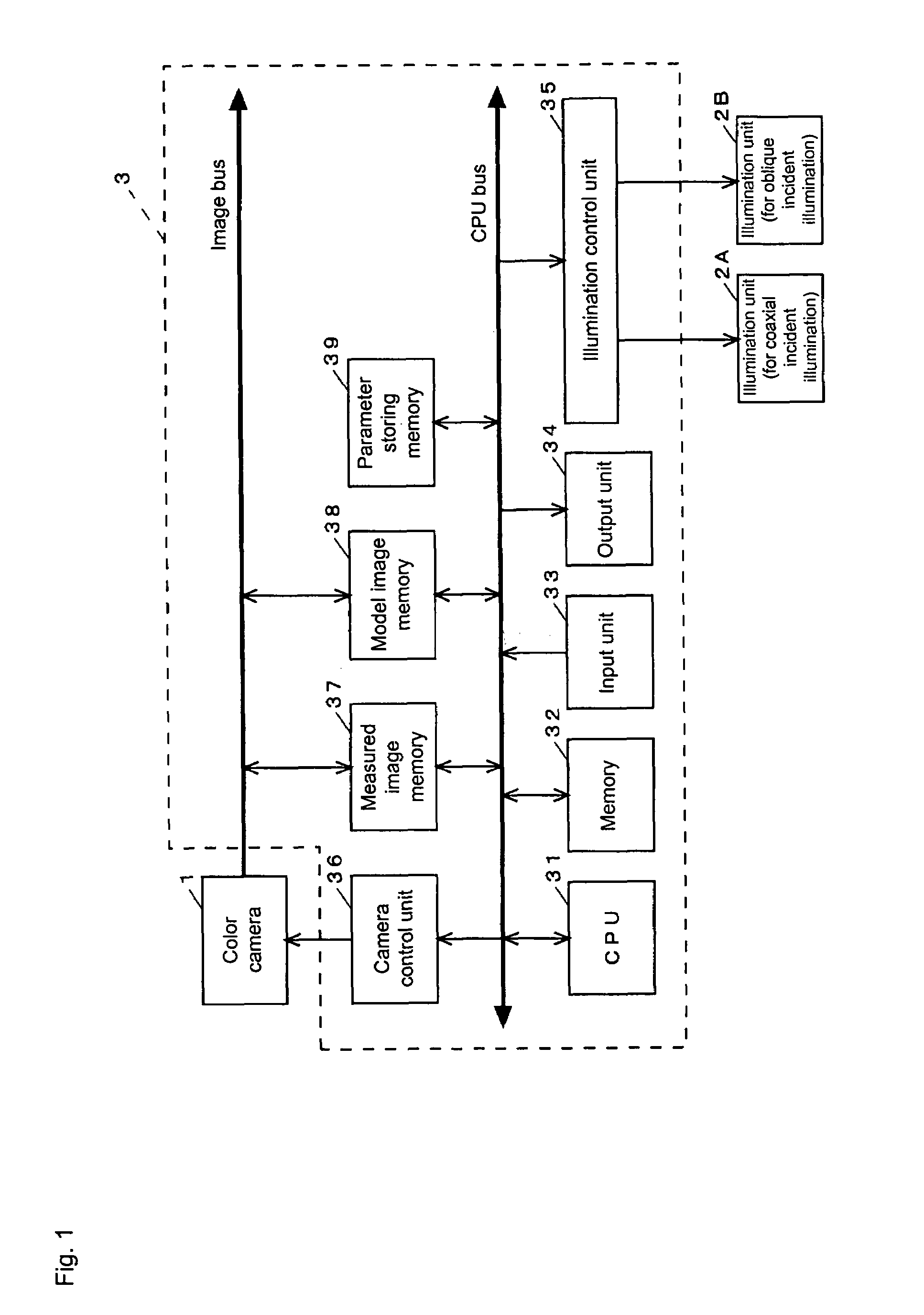
[0054]FIG. 1 shows an electric constitution of a defect inspection system according to one embodiment of the present invention.

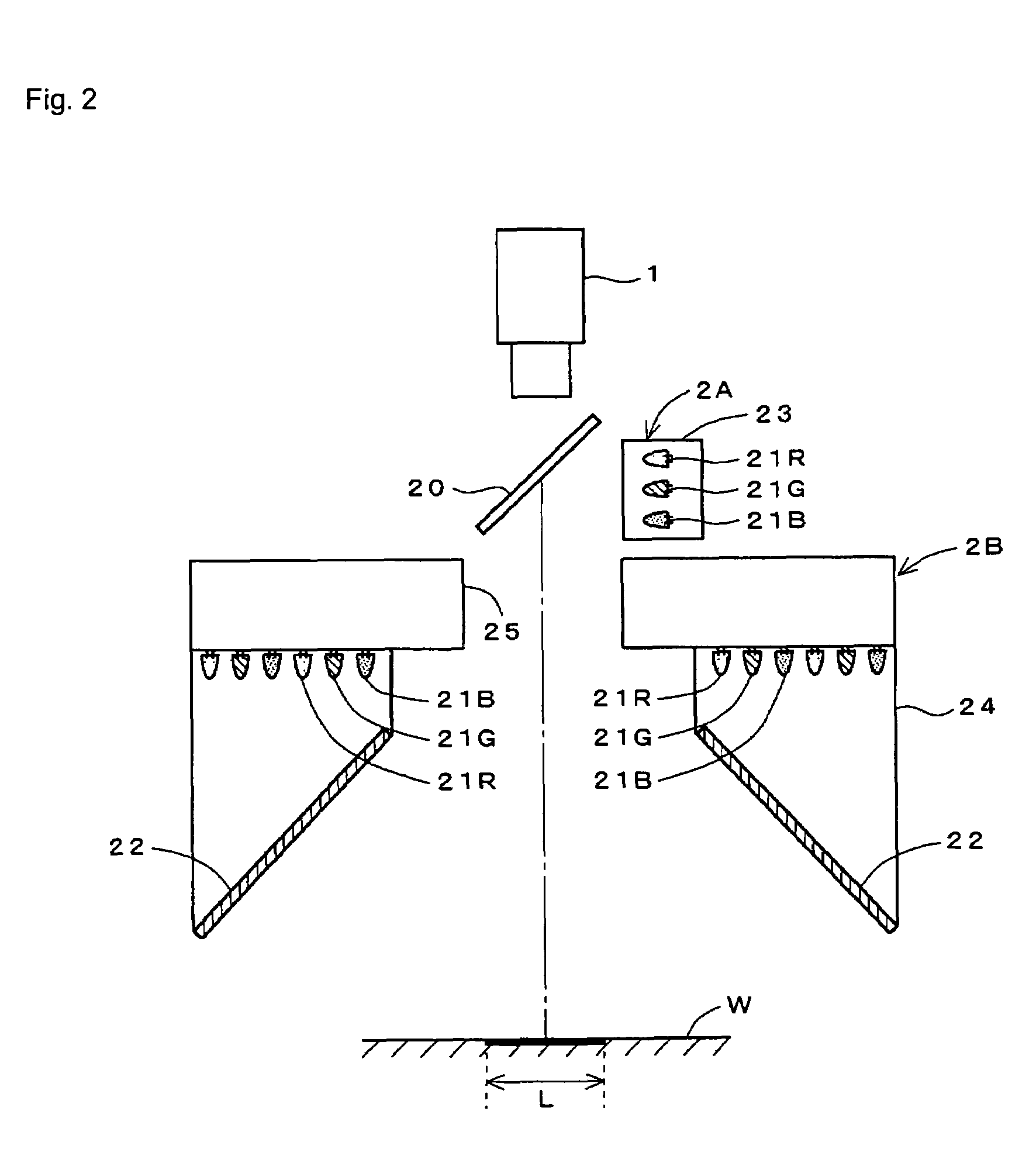
[0055]With an inspection object (work) which is a body formed of a colored resin and comprises a transparent coating layer on its surface, this defect inspection system detects a defect generated on a surface of the coating layer or between the coating layer and the work body.

[0056]The defect inspection system comprises a color camera 1 serving as an imaging device, two illumination units 2A and 2B, and a measuring unit 3 including a computer for main control. The illumination units 2A and 2B comprise a plurality of LED's as light sources, and the illumination unit 2A performs a coaxial incident illumination to the work and the illumination unit 2B performs an oblique incident illumination.

[0057]The measuring unit 3 comprises a CPU 31, a memory 32 storing a program, an input unit 33, an output unit 34, an illumination control unit 35, a camera control unit 3...


PUM

PropertyMeasurementUnit
reflection coefficientaaaaaaaaaa
defect inspectionaaaaaaaaaa

Abstract

A surface of a work to be inspected is irradiated with an illumination unit for a coaxial incident illumination and an illumination unit for an oblique incident illumination driven to take its image by a camera at the same time. Each of the illumination units and comprises light sources emitting color lights R, G and B, respectively. One of the three kinds of light sources is lighted in the illumination unit and one or two of the light sources which are not lighted in the illumination unit are lighted in the illumination unit.

Description

[0001]This application claims priority from Japanese patent applications JP P2005-111536, filed on Apr. 8, 2005, and JP P2006-062505, filed on Mar. 8, 2006. The entire contents of each of the aforementioned applications are incorporated herein by reference.BACKGROUND OF THE INVENTION[0002]1. Field of the Invention[0003]The present invention relates to a technique for inspecting whether an irregular defect or a color defect is generated on a surface of an object to be inspected which is formed of a material having a high regular reflectance (a resin, metal or the like).[0004]2. Description of the Related Art[0005]It is very important for a product which places a particular emphasis on its design such as a car or a home appliance to have no irregularity in luster or color on its surface in view of enhancing its commercial value.[0006]Although a surface of such product is made of a colored resin or metal, the surface could have an irregular defect or a color defect.[0007]The irregular ...

Claims


Application Information

Patent Timeline
Patent Type & Authority Patents(United States)
IPC IPC(8): G01N21/00G06V10/145
CPCG01N21/8806G01N21/94G06K9/2036G06T7/0006G01N2021/8825G06T2207/30136G06V10/145A22C21/06A22C21/0053A22C21/0023
Inventor OKABE, HIROSHIMATSUMOTO, TOSHIHIKO
Owner ORMON CORP
Why Eureka
Try Eureka