
Memory and operation method thereof

a technology of memory and operation method, applied in the field of memory, can solve the problems of reducing reading efficiency, data bubble generation, and inability to instantaneously provide the current required for operating the next row, and achieve the effect of improving data selection efficiency and shortening the time interval for selecting rows

Active Publication Date: 2008-11-04
NAN YA TECH
View PDF7 Cites 7 Cited by
  • Summary
  • Abstract
  • Description
  • Claims
  • Application Information

AI Technical Summary

Benefits of technology

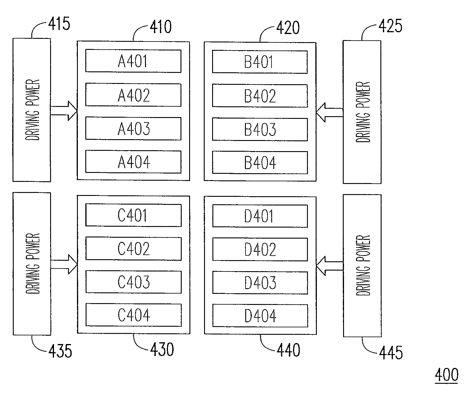
The present invention is a memory that improves data selection efficiency by using different tRRD times to shorten the time interval for selecting rows in different memory groups. The memory also divides its banks into different memory groups with independent driving power to decrease the tRRD time between memory groups. The method for operating the memory includes selecting rows in one memory group based on one active signal and selecting rows in another memory group based on another active signal, with a smaller inter-group interval than an intra-group interval. The memory structure and the selection method of the present invention improve data reading speed and minimize the generation of bubbles to prevent wasting system resources.

Problems solved by technology

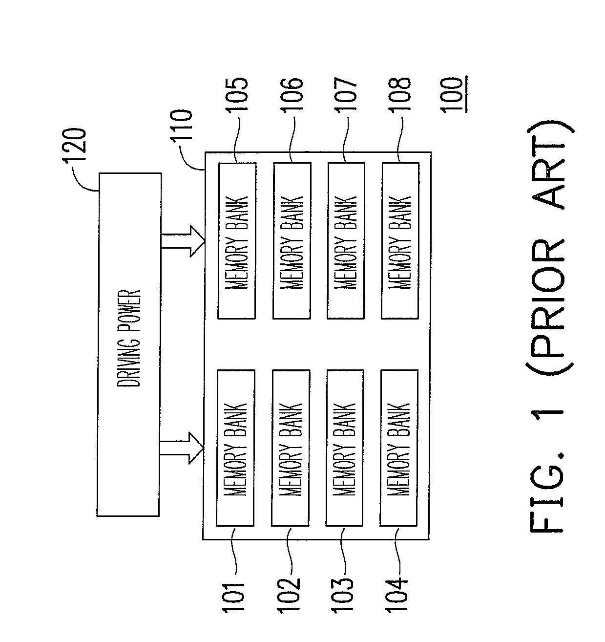
Since the operating frequency of DRAM is very fast, the driving capacity of a single driving power 120 is unable to instantaneously provide the current required for operating the next row.
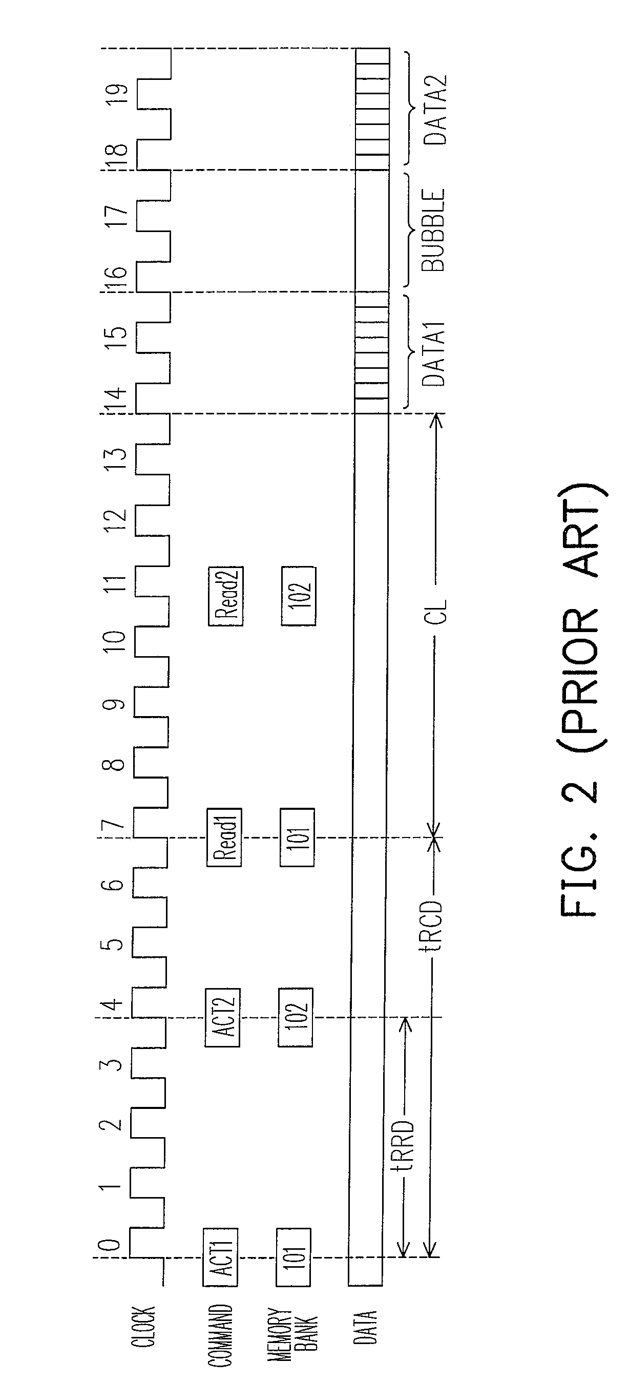
As a result, when the tRRD time is greater than the tCCD time (CAS to CAS delay), the memory 100 is unable to read data consecutively, resulting in bubbles.
Similarly, regardless of whether the memory 110 reads data from the same memory bank (any of the memory banks 101˜108) or from different memory banks 101˜108, data bubbles are generated because the tRRD time is greater than the tCCD time, lowering the reading efficiency and wasting the system resources.

Method used


Image

  • Memory and operation method thereof
  • Memory and operation method thereof
  • Memory and operation method thereof

Examples


Embodiment Construction

[0025]FIG. 3 is a schematic diagram illustrating a memory structure according to one embodiment of the present invention. A memory 300 includes driving powers 330 and 340, and memory groups 310 and 320. Herein, the driving power 330 is coupled to the memory group 310 and the driving power 340 is coupled to the memory group 320. The memory group 310 includes memory banks A301˜A304. The memory group 320 includes memory banks B301˜B304. In other words, the memory 300 divides memory banks into A301˜A304 and B301˜B304. Further, different driving powers 330 and 340 are respectively installed to instantaneously provide the operating voltage required by the memory 300. The driving powers 330 and 340 are independent voltage sources. However, the power lines can be connected or arranged individually. When the memory 300 needs to read the data in the memory banks A301˜A304, the driving power 330 provides the operating voltage to the corresponding memory cells in the memory banks A301˜A304 to p...


PUM


Abstract

A memory and an operation method thereof are provided. The present invention divides memory banks of the memory into a plurality of memory groups, wherein each memory group has an independent driving power for providing an operating voltage to the corresponding memory bank in the memory group. The present invention specifies two tRRD times which are an inter-group interval and an intra-group interval. The intra-group interval is the minimum time interval between selecting one row of memory banks in a memory group to selecting another row in the memory banks of the same memory group and the inter-group interval is the minimum time interval between selecting one row of the memory banks in one memory group to selecting another row in a different memory group. Further, the inter-group interval is shorter than or equal to the intra-group interval.

Description

CROSS-REFERENCE TO RELATED APPLICATION[0001]This application claims the priority benefit of Taiwan application serial no. 96111250, filed Mar. 30, 2007. All disclosure of the Taiwan application is incorporated herein by reference.BACKGROUND OF THE INVENTION[0002]1. Field of the Invention[0003]The present invention relates to a memory, and more particularly, to a dynamic random access memory (DRAM) having different row to row delay times (tRRD time, hereinafter) and an operation method thereof.[0004]2. Description of Related Art[0005]A conventional semiconductor memory device usually includes a plurality of memory banks. Herein, each memory bank has the same storage space (i.e. having the same number of memory cells) and the same storage capacity. Particularly, the widely used dynamic random access memory (abbreviated as DRAM) is a standard memory structure that usually includes a plurality of memory banks having the same capacity. FIG. 1 is a schematic view illustrating a convention...

Claims


Application Information

Patent Timeline
Patent Type & Authority Patents(United States)
IPC IPC(8): G11C8/00
CPCG11C8/18G11C8/12
Inventor CHANG, CHUAN-JENLIU, WEI-LI
Owner NAN YA TECH
Learn More