
Method and apparatus for data transmission in a mobile telecommunication system supporting enhanced uplink service

a mobile telecommunication system and data transmission technology, applied in the direction of transmission monitoring, power management, line-transmission details, etc., can solve the problems of dch or e-dch transmission quality deterioration due to retransmission, total transmit power exceeding the maximum allowed power, etc., to achieve efficient control of the transmit power of each physical channel

Active Publication Date: 2008-11-04
SAMSUNG ELECTRONICS CO LTD
View PDF64 Cites 57 Cited by
  • Summary
  • Abstract
  • Description
  • Claims
  • Application Information

AI Technical Summary

Benefits of technology

The present invention provides a method and apparatus for efficiently controlling transmit power of each physical channel when a user equipment exceeds the maximum allowed power in a case of supporting a packet service through uplink channels. This allows for adjusting power of specific transmission channels when enhanced uplink dedicated channel data is retransmitted, as well as adjusting transmit powers of different channels based on transmission conditions and priorities. This results in improved data transmission efficiency and reduced power consumption.

Problems solved by technology

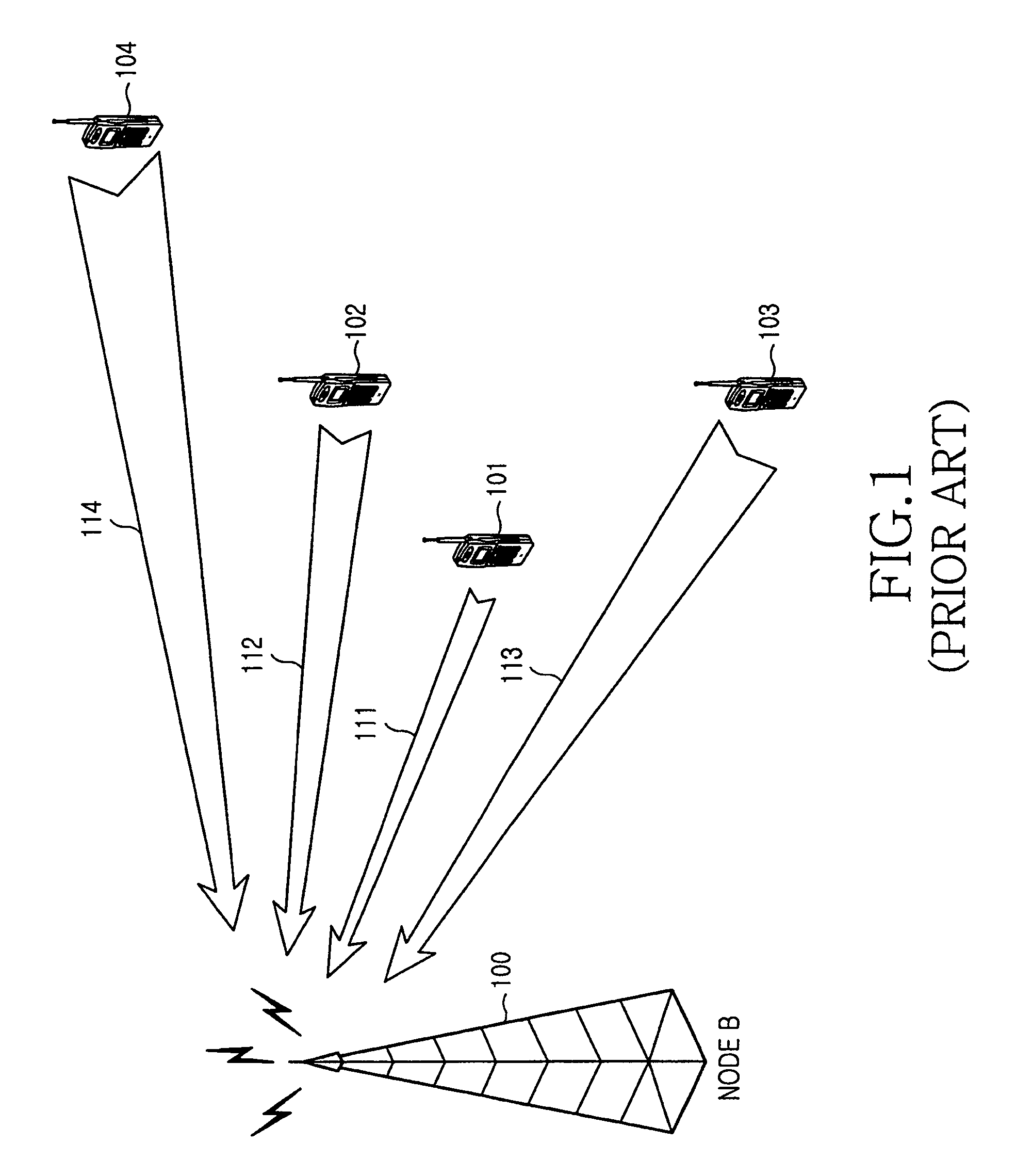
In such situations, if a UE uses the same power as that of the initial transmission for retransmission of the E-DCH data, it is likely to result in total transmit power exceeding the maximum allowed power.
Although it is possible to transmit all the physical channels within the maximum allowed power by equally scaling down powers of all the physical channels while maintaining their power ratios, transmission qualities of the respective physical channels may not be ensured.
In particular, if the transmit powers of all the physical channels are always equally scaled in a case where the DCH and the E-DCH have different priorities from each other, transmission quality of the DCH or the E-DCH may deteriorate due to retransmission.
To give an example, even if the DCH is used for a voice call having higher priority, DCH data may be transmitted with a very low level of power in some time slots within one TTI due to retransmission of the E-DCH data having lower priority, which results in quality deterioration of the voice call.

Method used


Image

  • Method and apparatus for data transmission in a mobile telecommunication system supporting enhanced uplink service
  • Method and apparatus for data transmission in a mobile telecommunication system supporting enhanced uplink service
  • Method and apparatus for data transmission in a mobile telecommunication system supporting enhanced uplink service

Examples


example 1

[0056]In a first embodiment of the present invention, total transmit power is scaled by recalculating a gain factor of a specific channel, that is, an E-DPDCH such that the total transmit power does not exceed the maximum allowed power in an upper layer of a UE. According to this first embodiment of the present invention, when both E-DCH data and DCH data exist, the UE checks if the E-DCH data is retransmitted. If a result of the checking shows retransmission of the E-DCH data, a gain factor of the E-DPDCH to which the E-DCH is mapped is reset at the time of the transmission.

[0057]FIG. 7 illustrates procedures of setting transmit powers of physical layers of a UE in accordance with the first embodiment of the present invention.

[0058]Referring to FIG. 7, in step 601, a UE detects a transmission request of E-DPDCH / DPDCH / DPCCH data, including gain factors of the respective channels. In step 602, the UE having detected the transmission request estimates total transmit power Ptx using th...

example 2

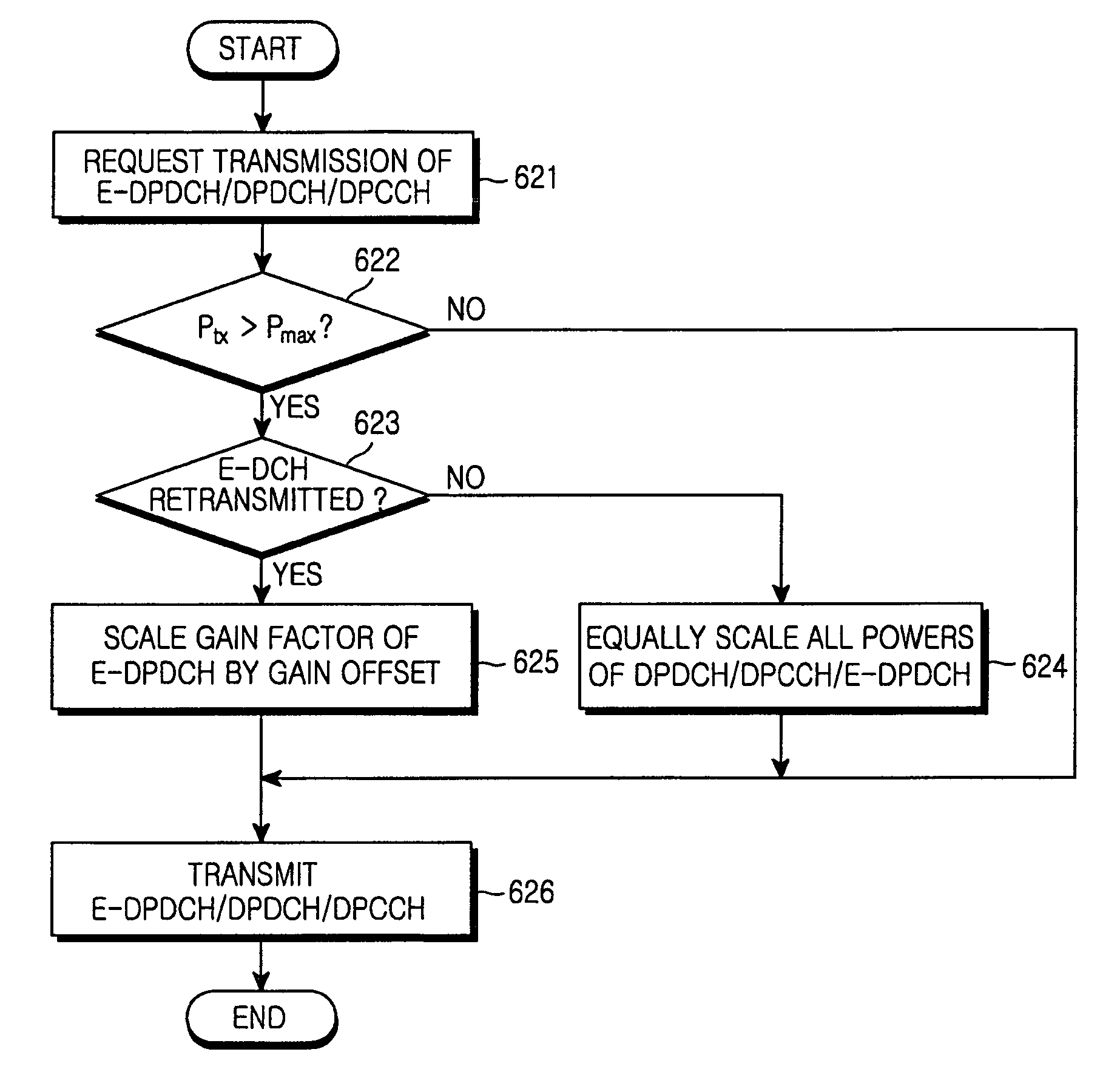
[0086]In a second embodiment of the present invention, if total transmit power exceeds the maximum allowed power in a case where E-DCH data is retransmitted, the total transmit power is scaled by reducing a gain factor of the E-DCH by a predetermined gain offset.

[0087]According to this second embodiment of the present invention, a new gain factor of an E-DPDCH is calculated by the following equation (Equation (2)) when the total transmit power exceeds the maximum allowed power.

βe=βe,ori×10(Δoffset / 10)

wherein Δoffset denotes the gain offset which can be set through signaling of an upper layer.

[0088]FIG. 9 illustrates procedures of setting transmit powers of physical layers of a UE in accordance with the second embodiment of the present invention.

[0089]Referring to FIG. 9, in step 621, a UE detects a transmission request of E-DPDCH / DPDCH / DPCCH data, comprising gain factors of the respective channels. In step 622, the UE having detected the transmission request estimates total transmi...

example 3

[0096]In a third embodiment of the present invention, a UE scales powers of the entire channels by selecting a gain factor of an E-DPDCH such that total transmit power does not exceed the maximum allowed power in consideration of retransmission. According to this third embodiment of the present invention, a gain factor is selected in a different manner from that of initial setting in TFC selection procedures when a DCH occurs at a point of time of retransmission differently from at initial transmission.

[0097]In particular, the UE checks transmit power on a slot unit basis for a plurality of channels to be transmitted and reduces the transmit power of a specific channel step by step according to priorities of the channels. The priority may be determined by whether the relevant channel is a channel, retransmission of which is ensured, a control channel or the like.

[0098]To facilitate understanding of this embodiment, an exemplary transmission environment will be described first.

[0099]...


PUM


Abstract

A method and an apparatus for data transmission in a mobile telecommunication system supporting an enhanced uplink service are provided. A Transport Format Combination (TFC) selector determines TF information for data to be transmitted through a first data channel not supporting Hybrid Automatic Repeat reQuest (HARQ) and a second data channel supporting HARQ, and determines gain factors for the first and second data channel, and first and second control channel carrying control information for the first and second data channel. The gain factors are input to a physical channel transmission controller, and the physical channel transmission controller scales-down the gain factor for the second channel if total transmit power required for transmission of the channels exceeds the predetermined maximum allowed power. A gain scaler adjusts transmit powers of the channels using the scaled gain factor and gain factors for the first data channel, the first control channel and the second control channel.

Description

PRIORITY[0001]This application claims the benefit under 35 U.S.C. 119(a) of applications entitled “Method and Apparatus for Data Transmission in Mobile Telecommunication System Supporting Enhanced Uplink Service” filed in the Korean Industrial Property Office on Jun. 9, 2004, Aug. 6, 2004, Sep. 14, 2004, Nov. 17, 2004 and Apr. 7, 2005 and assigned Ser. Nos. 2004-42300, 2004-62190, 2004-73552, 2004-93947 and 2005-29192, respectively, the entire contents of which are hereby incorporated by reference.BACKGROUND OF THE INVENTION[0002]1. Field of the Invention[0003]The present invention relates to a mobile telecommunication system supporting an enhanced uplink service. More particularly, the present invention relates to a power setting method and a power setting apparatus for transmitting data based on characteristics of uplink channels.[0004]2. Description of the Related Art[0005]An Enhanced-uplink Dedicated Channel (hereinafter referred to as ‘E-DCH’) has been proposed to improve the p...

Claims


Application Information

Patent Timeline
Patent Type & Authority Patents(United States)
IPC IPC(8): H04Q7/20H04B7/005H04J13/00H04W52/04H04W52/14H04W52/16H04W52/28H04W52/34H04W52/36H04W52/50
CPCH04W52/146H04W52/16H04W52/281H04W52/34H04W52/367H04W52/36H04W52/50
Inventor HEO, YOUN-HYOUNGLEE, JU-HOCHO, JOON-YOUNGKIM, YOUNG-BUMKWAK, YONG-JUN
Owner SAMSUNG ELECTRONICS CO LTD
Learn More