
Vehicular towing apparatus using air lift

a technology of air lift and towing equipment, which is applied in the field of land vehicles, can solve the problems of unduly endangered second drivers, inability to maintain the spacing between the two vehicles, and limitations of modern automatic transmission design, so as to improve the tracking of the towed vehicle, improve safety, and reduce the skill needed

Inactive Publication Date: 2008-11-11
TRANSPORT SYST HLDG CO LLC +2
View PDF4 Cites 5 Cited by
  • Summary
  • Abstract
  • Description
  • Claims
  • Application Information

AI Technical Summary

Benefits of technology

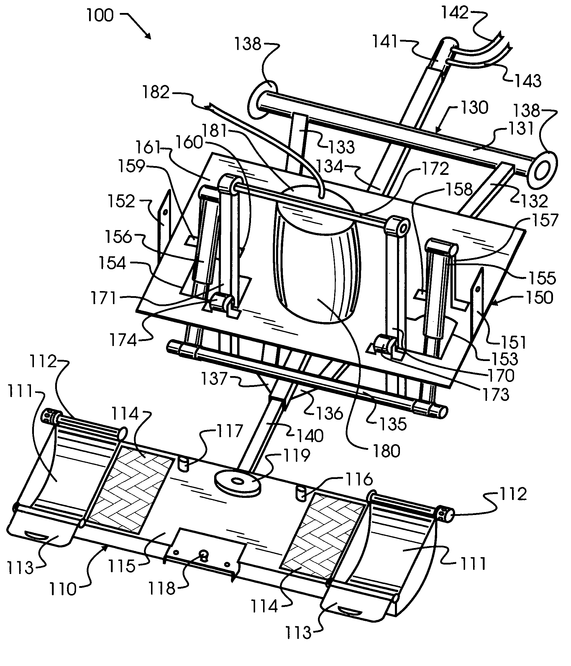
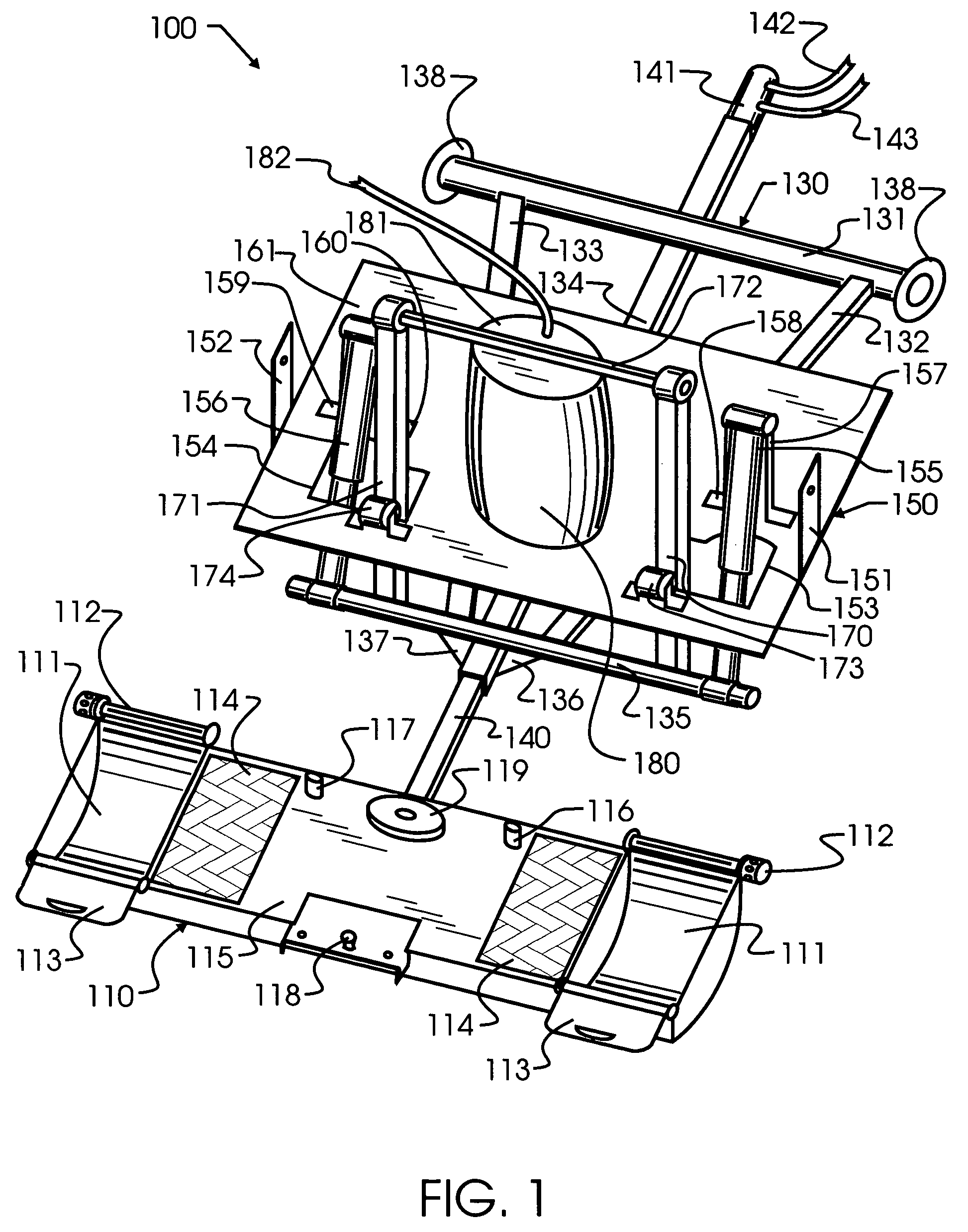
[0014]Exemplary embodiments and manifestations of the present invention solve the inadequacies of prior towing apparatus by providing an air bag in association with shock absorbers and a tow bar, which provides unprecedented cushion and following for towed vehicles. The air bag is most preferably a high capacity bag which may be selectively inflated and deflated, thereby allowing the tow connection to be raised and lowered at will. In addition, the tow bar may be extended or retracted as desired. Several platform attachments enable the towing apparatus to be used alternatively as an automobile tow bar, a support for motorcycles or bicycles, or other items that may be supported upon a platform. When not in use, the towing apparatus stows under the vehicle out of the way. The towing apparatus may also serve as a vehicle step or standard trailer ball attachment point.
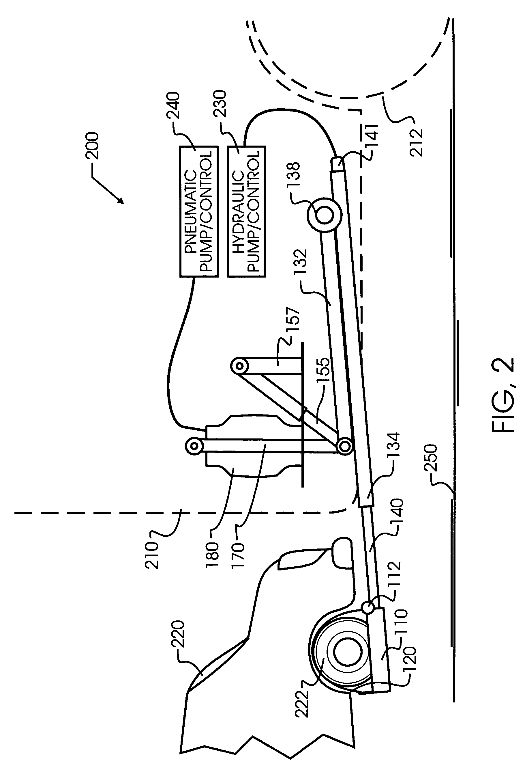
[0016]In a second manifestation, the invention is an apparatus for supporting a trailing load upon a towing means during transit. A framework attaches to the towing means. A shaft pivots about a transverse axis, and a variable pressure air bag rotates the shaft about the transverse axis, while simultaneously reducing a peak amplitude of acceleration forces about the transverse axis generated between towing means and trailing load during travel.
[0018]A first object of the present invention is to enable the towing and transport of diverse loads without requiring vehicles limited solely to the purpose of towing. A second object of the invention is to enable existing vehicles to be readily retrofit while maintaining the basic construction and configuration of essential components. A third object of the invention is to provide an apparatus for towing a land vehicle which serves to mechanically isolate the towing vehicle from the towed vehicle, thereby improving safety, ride and handling. A further object of the invention is to enable the towing apparatus to be stored when not in use without requiring separate storage facility or space, and for the towing apparatus to provide added benefit and utility to the towing vehicle when not in use as a towing apparatus. Yet another object of the present invention is for the apparatus to improve the tracking of a towed vehicle and to thereby reduce the skill needed to operate the towing vehicle and increase the safety of the towing process.

Problems solved by technology

While this approach may seem to be the simplest, and certainly requires a minimum of special equipment, the flaccid connector does not maintain spacing between the two vehicles.
In the event the second driver briefly loses attention at the same time that the front vehicle slows down, a serious accident may result.
In fact, history has demonstrated repeatedly that the second driver is unduly endangered.
A second limitation arises from the design of modern automatic transmissions.
In other words, if the trailing vehicle has a modern automatic transmission, simply shifting the transmission into neutral is not sufficient.
Towing the vehicle, even in neutral, may seriously damage the transmission.
Disconnecting the transmission is not a task which would be attempted by most persons, and there is no equipment provided in the flaccid connector approach for lifting vehicle drive wheels.
A ball somewhere within the draft connection is required, since the two vehicles will not always maintain the same planar relationship.
In spite of the many advantages of balls, which are very commonly used in trailers and in some vehicle to vehicle draft connections, the risk of damaging a modern vehicle with an automatic transmission by towing still remains.
While this approach works for special purposes such as delivery of new cars or the transport of racing vehicles, it does require that the towing and transport vehicle be very large and have sufficient space for a second vehicle.
This limits the use of the towing and transport vehicle to only a few specialized needs, and requires a substantial financial investment in the towing vehicle and storage space when not in use.
Unfortunately, while this technique offers great flexibility in towing very diverse vehicles, a dedicated vehicle with a large boom and winch system is also required.
Unfortunately, there are still several drawbacks which arise.
First of all, the trailer again requires extra equipment, and also storage space when not in use.
A second drawback stems from the extra width required within the small trailer.
This extra width is generally undesirable, and, where the towed vehicle is already approaching the legal limits for width, this will lead to an oversize restriction.
Further, the set of wheels on the small trailer require maintenance, over and above the maintenance already required by the separate vehicle wheels.
A third drawback is actually characteristic of all ball and hitch connections.
When a towed vehicle articulates with respect to the towing vehicle, which may be induced for example by unevenness in the road surface, there is nothing provided to absorb the changes in direction between the towing and towed vehicles.
If the transition from parking lot to roadway is sufficiently severe, and the towing vehicle and trailer are close in weight or the towing vehicle has a longer distance between the rear wheels and the hitch, this can actually lead to dangerous lifting of the towing vehicle front wheels or loss of traction.
Furthermore, the additional shifting of the towing vehicle reduces the comfort of the ride by transmitting these forces from the hitch into the vehicle cabin.
Nevertheless, each of these connections only serve as a shock absorber or adjunct to a standard type of hitch, and do not expand or enhance the application of the connection equipment, nor do they fully address the objectives of the present invention.

Method used


Image

  • Vehicular towing apparatus using air lift
  • Vehicular towing apparatus using air lift
  • Vehicular towing apparatus using air lift

Examples


Embodiment Construction

[0022]Primary structural assembly 100 of preferred embodiment vehicular towing apparatus 200 includes a towing and transporting platform 110, a framework 130, and a suspension assembly 150. Towing and transporting platform 110 is provided with small ramps 113 and wheel receiving cusps 111 which will serve to support the front wheels 222 of vehicle 220. As can be best seen from FIG. 2, a strap 120 may be provided to securely attach tire 222 to wheel cusp 111 during transport. In the preferred embodiment, a ratchet 112 is provided to tighten strap 120, as is known in the general hardware field of tie-down devices. Alternative methods of attachment between vehicle 220 and platform 110 are contemplated, and will be obvious to those skilled in the art. For example, while a flaccid strap is most preferred, a chain-type fastener and chain may also be used. Furthermore, other vehicles besides passenger cars and utility vehicles may be transported. In such instances, different geometries of ...


PUM


Abstract

A vehicular towing apparatus incorporates an air bag in association with shock absorbers and a tow bar. The air bag may be selectively inflated and deflated, allowing the tow bar to be raised and lowered at will. In addition, the tow bar may be extended or retracted as desired. Several platform attachments enable the towing apparatus to be used alternatively as an automobile tow bar, a support for motorcycles or bicycles, or other items that may be supported upon a platform. The towing apparatus retracts under the vehicle, and may also serve as a vehicle step or standard trailer ball attachment point.

Description

CROSS REFERENCE TO RELATED APPLICATIONS[0001]This application claims priority to U.S. Provisional Application serial No. 60 / 176,907 filed Jan. 20, 2000, the contents which are incorporated herein by reference in entirety, and is a continuation application of allowed U.S. utility application Ser. No. 09 / 767,598 filed on Jan. 22, 2001 copending herewith and scheduled to be granted as U.S. Pat. No. 6,692,218, on Feb. 17, 2004, the contents which are incorporated herein by reference in entirety.BACKGROUND OF THE INVENTION[0002]1. Field of the Invention[0003]The present invention pertains to land vehicles generally, and more specifically to an apparatus used to interconnect a towing and transporting vehicle to a transported load. In one embodiment, the transported load is a second land vehicle, and may include such diverse vehicles as automobiles, utility trucks, motorcycles, trailers and other vehicles and non-vehicles. In a more specific embodiment, the invention pertains to a multi-pu...

Claims


Application Information

Patent Timeline
Patent Type & Authority Patents(United States)
IPC IPC(8): B65G1/00B60P3/12
CPCB60P3/125
Inventor GRILE, MERRILL L.
Owner TRANSPORT SYST HLDG CO LLC
Learn More