Laser device coupled to a cavity by optical feedback for detecting gas traces

a laser device and a cavity technology, applied in the direction of optical radiation measurement, interferometric spectrometry, instruments, etc., can solve the problems of impossible or very complex implementation of direct measurement by spectroscopy in the resonant cavity

Inactive Publication Date: 2008-11-11
UNIV GRENOBLE ALPES
View PDF19 Cites 42 Cited by
  • Summary
  • Abstract
  • Description
  • Claims
  • Application Information

AI Technical Summary

Benefits of technology

[0017]According to an embodiment of the present inven

Problems solved by technology

Unfortunately, in practice, such methods of direct measurement by spectr

Method used


Image

  • Laser device coupled to a cavity by optical feedback for detecting gas traces
  • Laser device coupled to a cavity by optical feedback for detecting gas traces
  • Laser device coupled to a cavity by optical feedback for detecting gas traces

Examples


Embodiment Construction

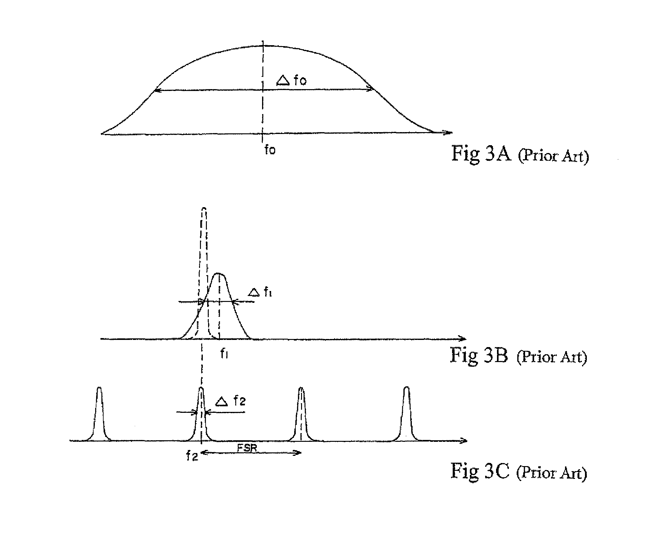
[0030]Before describing the present invention, the applicant insists on recalling that, in the field of optical spectroscopy, terms such as thin line, monomode system, etc. often have different meanings according to authors. The vocabulary which will be used herein will thus be specified hereafter in relation with FIGS. 3A to 3C.

[0031]FIG. 3A shows the intensity of an absorption line of a gas species according to frequency. The line has a central frequency f0 and a width Δf0. As an example, the absorption line at 1651 nm of methane has an absorption line width Δf0=4.4 GHz (which corresponds to a 0.04-nm wavelength range).

[0032]A continuous-wave laser such as a laser diode or another semiconductor laser with a settable frequency will emit a line f1 of width Δf1 such as shown in FIG. 3B. Generally, Δf1 will be much smaller than width Δf0 of the absorption line, and this case will always be considered herein.

[0033]Further, as illustrated in FIG. 3C, a resonant optical cavity of given l...


PUM


Abstract

A device of detection of gas in trace amounts by a semiconductor laser coupled to a resonant optical cavity containing a chemical species to be analyzed. The device comprises a resonant optical cavity containing a chemical species to be analyzed; a semiconductor laser, coupled by optical feedback to the optical cavity and capable of being frequency-scanned; a means for adjusting the laser-cavity coupling rate; a means for finely adjusting the optical feedback phase; and a means for measuring the light transmitted by the cavity.

Description

RELATED APPLICATIONS[0001]This application is a National Stage of International Application PCT / FR02 / 03438, filed on Oct. 9, 2002, which claims priority of French Application No. 01 / 13052 filed on Oct. 10, 2001.BACKGROUND OF THE INVENTION[0002]1. Field of the Invention[0003]The present invention relates to the detection of gas in trace amounts. It more generally relates to a spectroscopy absorption measurement method in a resonant cavity.[0004]2. Discussion of the Related Art[0005]FIG. 1 illustrates the basic diagram of a method of spectroscopy absorption measurement in a resonant cavity. Light is emitted by a laser 1 in a resonant optical cavity 2 via an optical coupling system 3. The light coming out of the resonant cavity is received by a photodetector 4 and is sent to an analyzer 5. If the laser frequency varies, there will be a maximum of the signal received by the photodetector for each cavity mode. If the cavity contains a chemical species exhibiting an absorption line at the...

Claims


Application Information

Patent Timeline
IPC IPC(8): G01N21/00G01B9/02G01N21/39
CPCG01N21/39H01S3/005H01S3/0064H01S3/10092
Inventor MORVILLE, JEROMEROMANINI, DANIELECHENEVIER, MARC
Owner UNIV GRENOBLE ALPES
Why Eureka
Try Eureka