
Vacuum lamination apparatus and vacuum lamination method

a vacuum lamination and vacuum lamination technology, applied in the direction of presses, pv power plants, manufacturing tools, etc., can solve the problems of difficult to obtain sufficient rigidity of the apparatus, external appearance defects, and worsening of the global environment, so as to improve productivity, simple structure, and increase the secondary sectional moment of the cover sheet

Inactive Publication Date: 2008-11-18
FUJI ELECTRIC CO LTD
View PDF20 Cites 3 Cited by
  • Summary
  • Abstract
  • Description
  • Claims
  • Application Information

AI Technical Summary

Benefits of technology

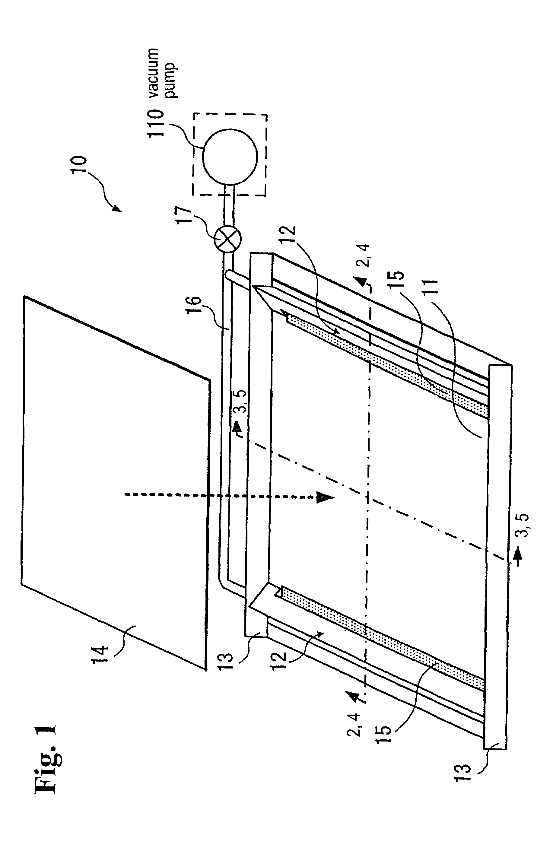
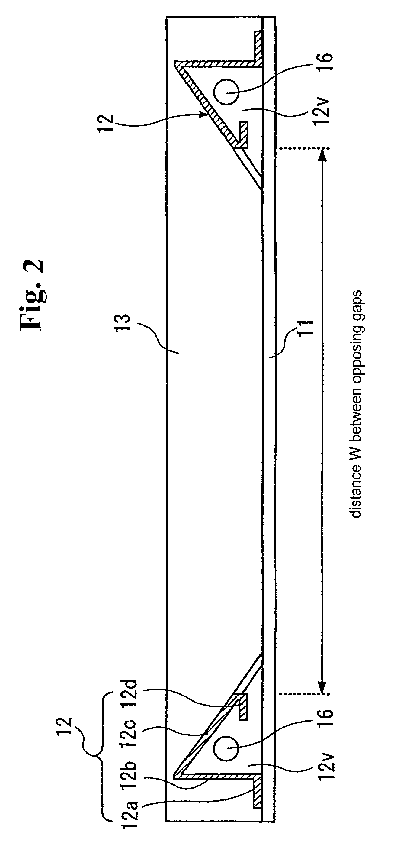
The present invention is a vacuum lamination apparatus for performing a vacuum lamination process on a laminate material. The apparatus includes a base plate, evacuation members, end plates, and a cover sheet. The evacuation members are arranged on the base plate at opposite sides of the lamination material and have evacuation ports at opposing sides of the base plate by a constant distance. The end plates are hermetically fixed to the ends of the evacuation members in the longitudinal direction. The cover sheet covers the lamination material and the evacuation members to form a lamination space for the vacuum lamination process. The apparatus creates evacuation spaces in the evacuation members and allows air in the processing space to be evacuated through the evacuation ports. The guides bend the peripheral edge portions of the cover sheet where the evacuation members are not disposed, thereby increasing secondary sectional moment of the cover sheet and closely attaching it. The apparatus can handle a large laminate module, improve productivity, reduce cost, and suppress air leakage, resulting in high-quality vacuum lamination.

Problems solved by technology

A large amount of fossil fuel has been consumed since Industrial Revolution, and the global environment has been worsened due to air pollution and global warming by CO2.
A leakage may lead to insufficient degassing of the materials of the solar cell module component 1007, thereby generating an air bubble in the solar cell module and causing an external appearance defect.
However, even if the base plate and the tube are firmly integrated together with welding, it is difficult to obtain sufficient rigidity of the apparatus as a whole as a tube shape member generally does not provide high rigidity.
Further, it is necessary to provide a buffer member for protecting the cover sheet, so that the numbers of parts and manufacturing steps increase, thereby increasing cost of the apparatus.
Also, it is difficult to form a large number of the exhaust holes in the tube, thereby deteriorating evacuation performance.

Method used


Image

  • Vacuum lamination apparatus and vacuum lamination method
  • Vacuum lamination apparatus and vacuum lamination method
  • Vacuum lamination apparatus and vacuum lamination method

Examples


first embodiment

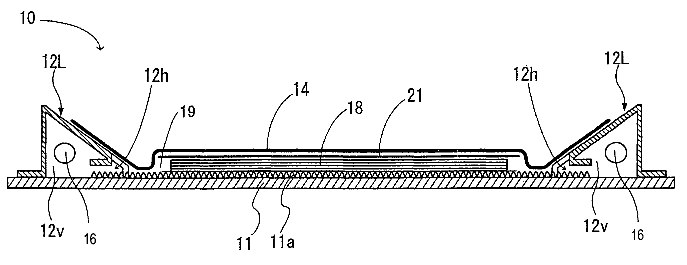
[0063]As shown in FIG. 7, in the lamination process of the lamination apparatus of the first embodiment, two peripheral sides of the cover sheet 14 contact the base plate 11 to hold the processing space in an airtight condition. Here, the cover sheet 14 closely contacts the base plate 11 only at an inner edge of a contact area with vacuum differential pressure, while outside of the inner edge just loosely contact with the atmospheric pressure. The closely contacting edge works as a seal point. A region between the seal points generated at the two peripheral sides of the cover sheet 14 develops vacuum differential pressure.

second embodiment

[0064]When the vacuum lamination apparatus is heated after evacuation, the cover sheet 14 expands due to heat. As shown in FIG. 8, left and right ends of the two peripheral sides of the cover sheet 14 are constrained by the inclined parts of the evacuation members 12. As a result, a portion thermally expanded is lifted up from the base plate 11, thereby losing the close contact at the seal point. With the structure, the cover sheet 14 contacts the base plate 11, so that the secondary sectional moment of the cover sheet 14 is not enough to prevent the expanded portion from lifting along the seal point. As a result, leakage may be generated through the lifted seal point, thereby lowering vacuum in the processing space. Further, the cover sheet 14 is composed of an elastic material such as a silicone resin, so that it is difficult to form a shape having desired secondary sectional moment beforehand. The vacuum lamination apparatus according to the invention is designed to prevent such ...


PUM


Abstract

A vacuum lamination apparatus for performing a vacuum lamination process on a lamination material includes a base plate having two opposing sides for placing the lamination material; and evacuation members having an approximately triangular cross-section and fixed hermetically to the base plate at the two opposing sides. Each of the evacuation members has an evacuation port with a constant distance relative to the base plate. The vacuum lamination apparatus also includes end plates fixed hermetically to ends of each of the evacuation member, and a cover sheet placed on the base plate for covering the lamination material and the evacuation members to form a lamination space for performing the vacuum lamination process.

Description

BACKGROUND OF THE INVENTION AND RELATED ART STATEMENT[0001]The present invention generally relates to a vacuum lamination apparatus and a vacuum lamination method. In particular, the present invention relates to a vacuum lamination apparatus and a vacuum lamination method of applying a vacuum lamination process to a member to be laminated such as a component of a solar cell module.[0002]A large amount of fossil fuel has been consumed since Industrial Revolution, and the global environment has been worsened due to air pollution and global warming by CO2. Accordingly, in recent years, environmental consciousness has been increased in the global scale. In this circumstance, solar cells have been expected to be as safe, easy to handle, and clean energy source. There are several types of solar cells including a single crystal silicon solar cell, a polycrystalline silicon solar cell, an amorphous silicon solar cell, and a compound semiconductor solar cell. Among these types of solar cells...

Claims


Application Information

Patent Timeline
Patent Type & Authority Patents(United States)
IPC IPC(8): B32B37/10B30B5/02
CPCB32B37/1018
Inventor YOKOYAMA, YASUHIRO
Owner FUJI ELECTRIC CO LTD
Learn More