
Superconducting electric motor

a superconducting electric motor and superconducting technology, applied in the direction of synchronous motors, magnetic circuit rotating parts, magnetic circuit shape/form/construction, etc., can solve the problems of rotor torque, significant increase in the field magnetomotive force generated by the windings, and increase the flux and power density of the machines

Inactive Publication Date: 2008-11-18
AMERICAN SUPERCONDUCTOR
View PDF13 Cites 30 Cited by
  • Summary
  • Abstract
  • Description
  • Claims
  • Application Information

AI Technical Summary

Benefits of technology

[0014]A superconducting motor configured in this manner has numerous advantages including allowing continued operation—albeit at reduced power—of the motor. For example, the superconducting motors can be advantageously used as part of a ship propulsion system. In this application, if the cooling system used to cool the superconducting windings were to fail, the motor could be operated in the induction mode, allowing the ship to continue to travel at some fraction of its rated speed. When the cooling system problem is remedied, the superconducting motor is simply returned to its normal, full power, synchronous mode of operation.
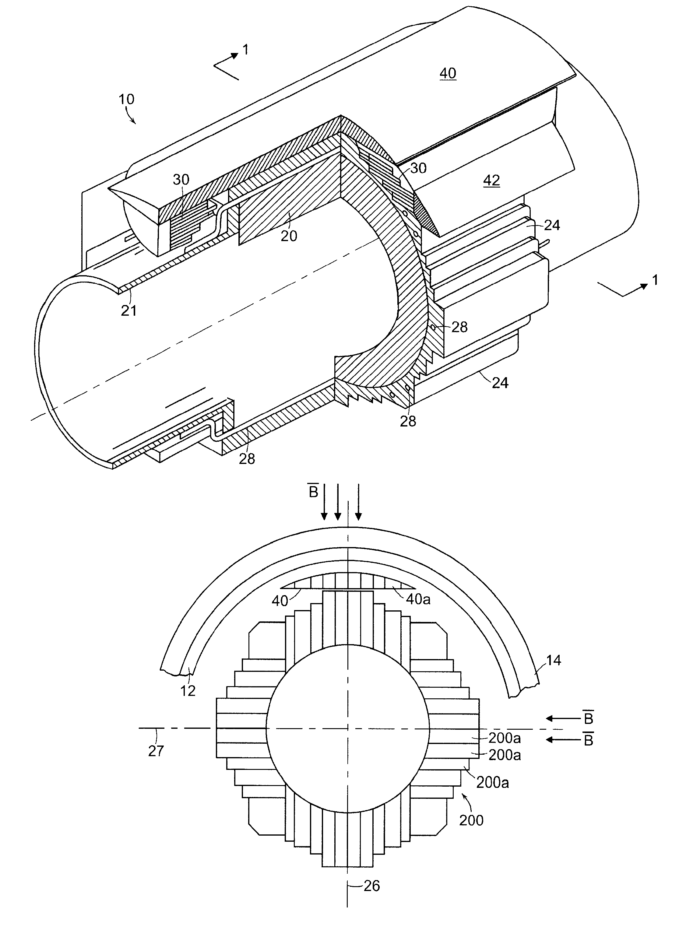
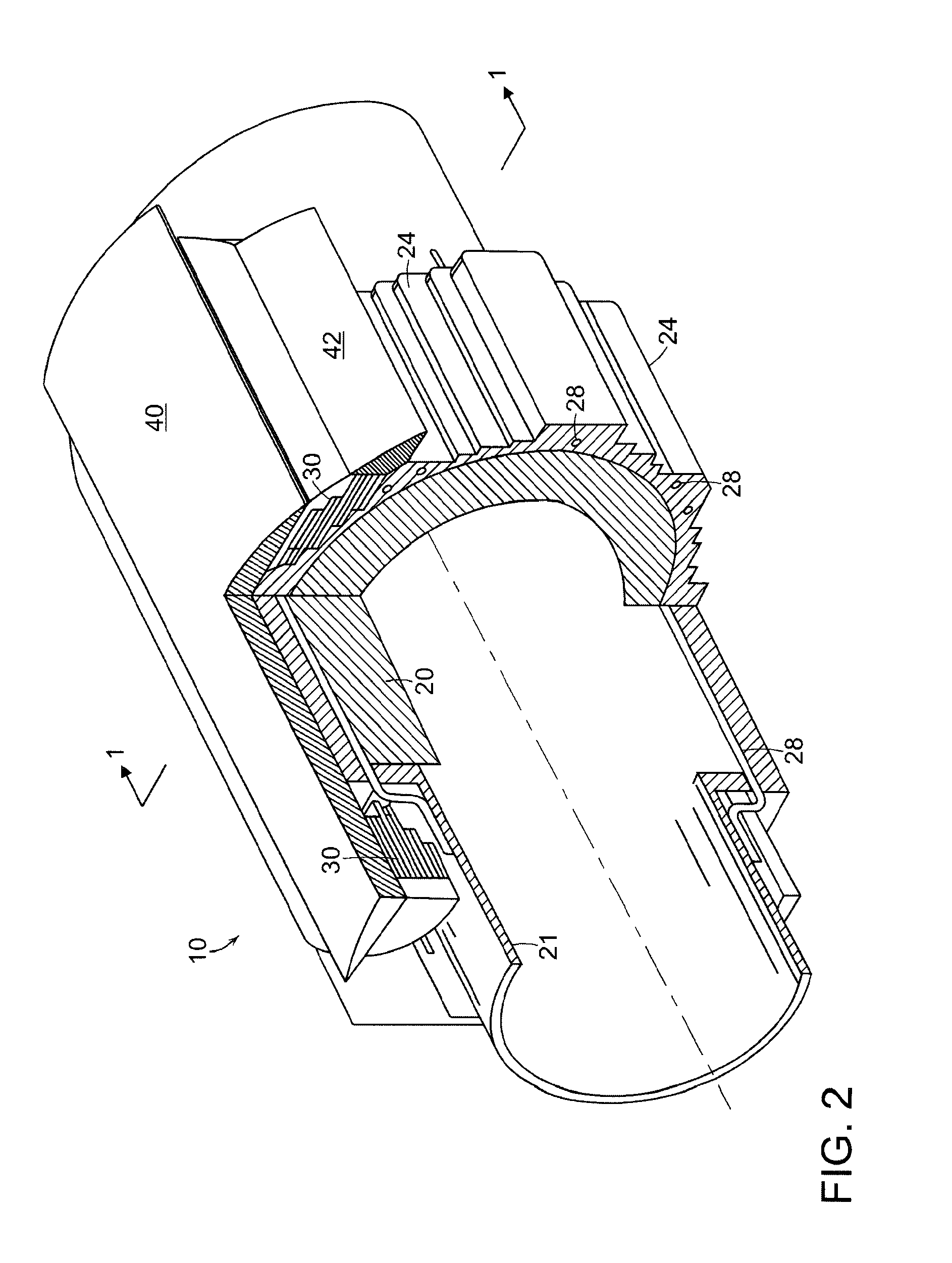
[0017]In one embodiment, at least a portion of the induction structure is spaced from the at least one superconducting winding by a thermal isolation vacuum region. That is, a portion of the induction structure is in the warm region of the rotor assembly, such as an electromagnetic shield member. The induction structure can also include a cryostat positioned between the thermal isolation vacuum region and the electromagnetic shield member. Thus, the cryostat not only serves to cool the superconducting windings of the rotor assembly, but also serves to support induced currents when the motor operates in the induction mode.

Problems solved by technology

Once that occurs, the magnetic field causes forces to act on the current carrying conductors, which results in a torque on the rotor.
The use of superconducting windings in these machines has resulted in a significant increase in the field magnetomotive forces generated by the windings and increased flux and power densities of the machines.

Method used


Image

  • Superconducting electric motor
  • Superconducting electric motor
  • Superconducting electric motor

Examples


Embodiment Construction

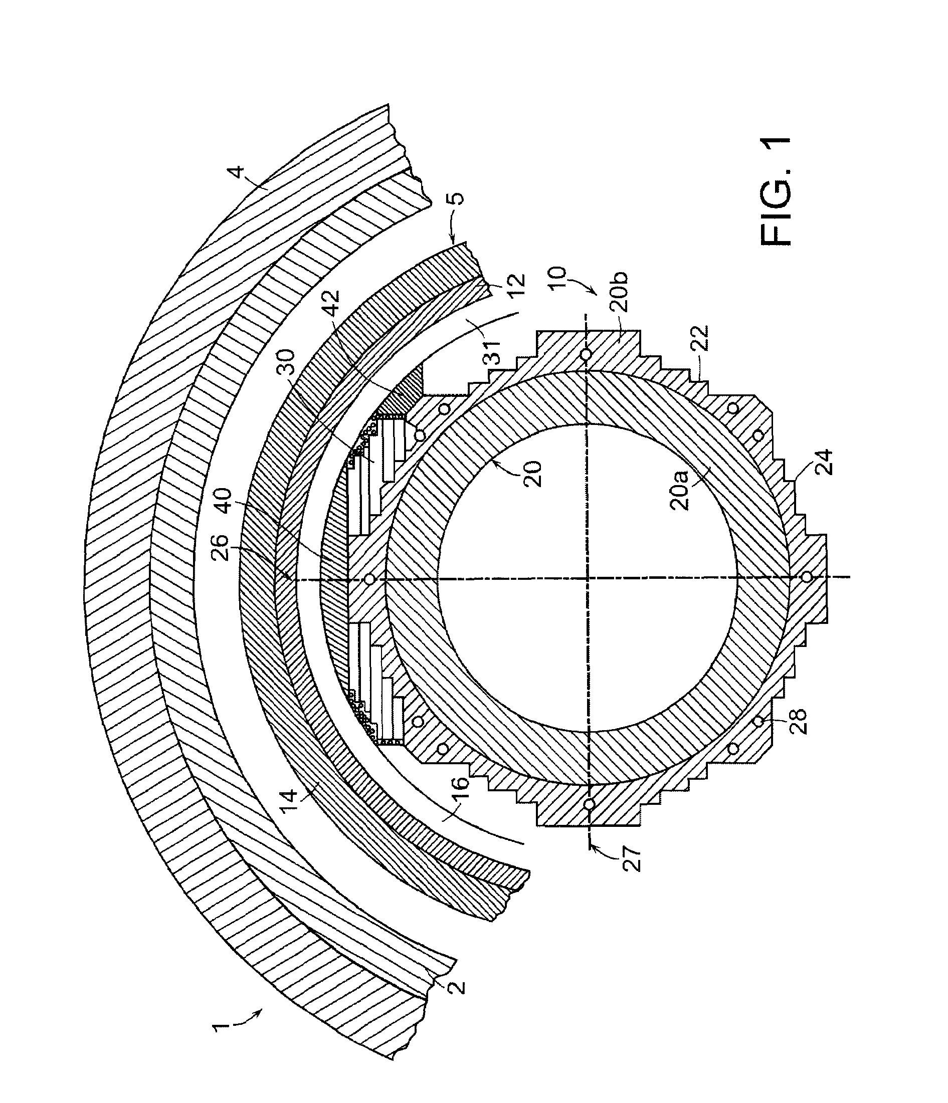
[0028]Referring to FIG. 1, a superconducting synchronous motor 1 includes a rotor assembly 5 having a four-pole topology surrounded by a cryostat 12 and an outer electromagnetic shield 14, both of which are radially spaced from a cold rotor section 10 of assembly 5 by a vacuum layer 16. Electromagnetic shield 14 is, in turn, surrounded by a three-phase stator winding 2 and a laminated flux shield 4, here formed of iron. In other embodiments, iron flux shield 4 could be replaced with a solid metallic shield made of a non-magnetic material (e.g., copper or aluminum). Electromagnetic shield 14 is fabricated from a preferably non-magnetic material (e.g., copper, aluminum, steel, etc.). Rotor cold section 10 also includes a cold support member 20 fabricated from a high-strength and ductile material (e.g., aluminum). As will be discussed in greater detail below, aside from their typical functions, cryostat 12, electromagnetic shield 14, and cold support member 20, in aggregate, serve an a...


PUM


Abstract

A superconducting motor which operates in a synchronous mode of operation, can also be operated in an induction mode in the event that the superconducting components of the motor lose their superconducting properties (e.g., due to cooling system failure). The superconducting electric motor includes a rotor assembly having at least one superconducting winding which, in operation, generates a flux path within the rotor assembly, and a support member which supports the at least one superconducting winding. The rotor assembly is configured to operate in a synchronous mode of operation at temperatures in which the superconducting winding exhibits superconducting characteristics and in a steady-state induction mode of operation at temperatures in which the superconducting winding exhibits non-superconducting characteristics.

Description

BACKGROUND OF THE INVENTION[0001]The invention relates to the construction and operation of superconducting electric machines, including superconducting electric motors.[0002]There are a wide variety of electric motors, including linear and rotary motors. Among the more popular rotary electric motors are AC induction and AC synchronous motors. With both motors, the manner in which the motor rotates involves the interaction of magnetic fields of the rotor and the stator.[0003]For the AC induction motor, the stator windings are usually connected to a supply in one or three phase form. By applying a voltage across the winding, a radial rotating magnetic field is formed. The rotor has layers of conductive strands along its periphery. The strands are generally short-circuited to form conductive closed loops. The rotating magnetic fields produced by the stator induce a current into the conductive loops of the rotor. Once that occurs, the magnetic field causes forces to act on the current ...

Claims


Application Information

Patent Timeline
IPC IPC(8): H02K9/00H02K3/46H02K17/26H02K19/14H02K55/04
CPCH02K19/14H02K55/04Y02E40/625Y02E40/60H02K19/12H02K2213/09
Inventor KALSI, SWARN S.
Owner AMERICAN SUPERCONDUCTOR
Learn More