LVDS input circuit with connection to input of output driver

a technology of output driver and input circuit, which is applied in logic circuit coupling/interface arrangement, logic circuit coupling/interface with bidirectional operation, and pulse technique, etc., can solve the problem of double the number of connection requirements between a sending circuit and a receiving circui

Active Publication Date: 2008-11-18
TEXAS INSTR INC
View PDF9 Cites 3 Cited by
  • Summary
  • Abstract
  • Description
  • Claims
  • Application Information

AI Technical Summary

Problems solved by technology

The drawback of LVDS signaling is that it doubles the number of connection required between a sending circuit and a receiving circuit.

Method used


Image

  • LVDS input circuit with connection to input of output driver
  • LVDS input circuit with connection to input of output driver
  • LVDS input circuit with connection to input of output driver

Examples


Embodiment Construction

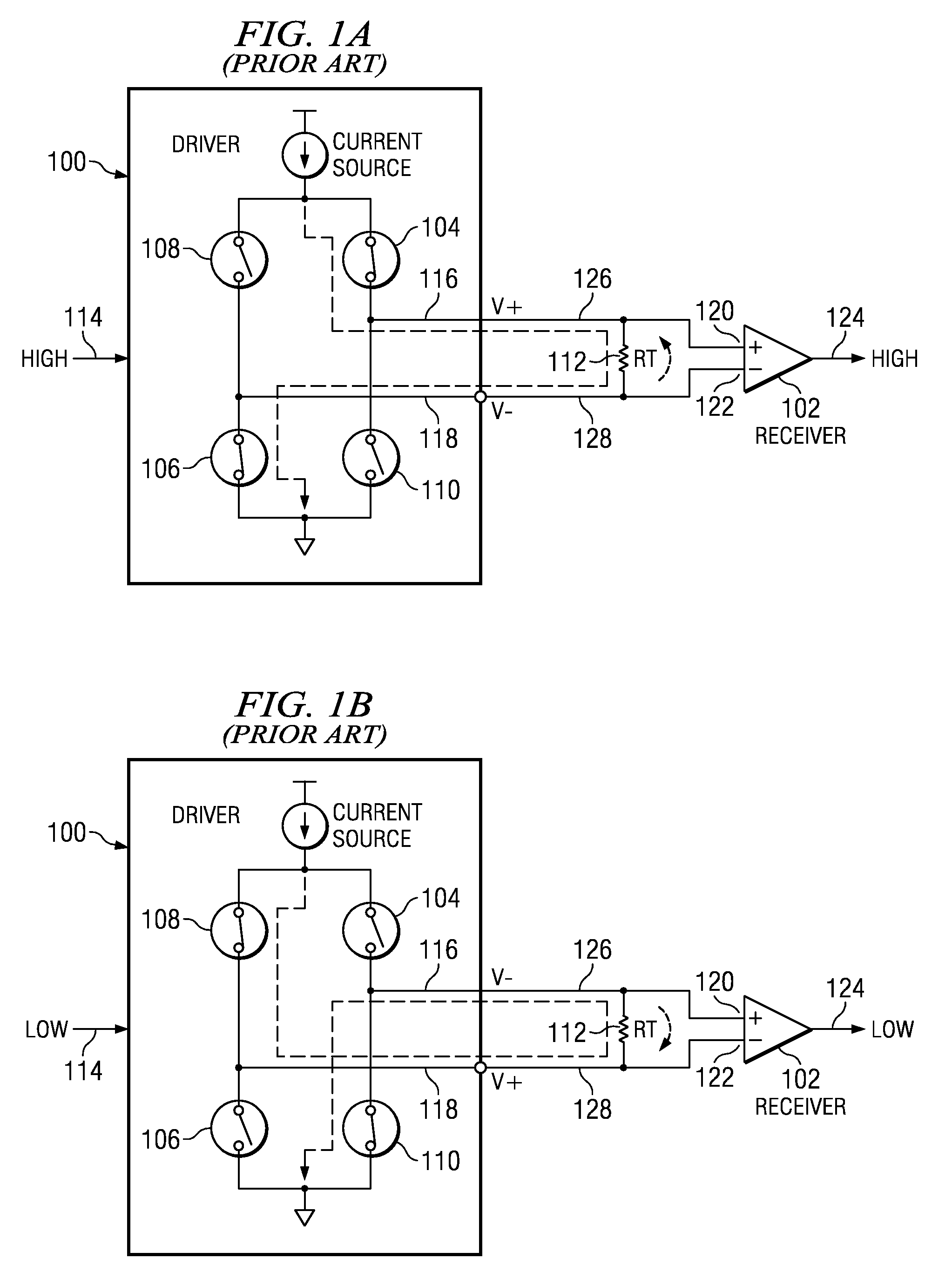
[0044]FIGS. 1A and 1B illustrate the connection between a conventional LVDS driver 100 and receiver 102. The driver has an input 114, a non-inverting output 116 and an inverting output 118. The driver is comprised of transistors, indicated as switches 104-110, that are controlled by the input 114. The receiver has a non-inverting input 120, an inverting input 122, and an output 124. A first signal path connection 126 is formed between driver output 116 and receiver input 120. A second signal path connection 128 is formed between driver output 118 and receiver input 122. A termination resistor 112 is placed across the receiver inputs 120 and 122.

[0045]In FIG. 1A, a logic high is input to the driver. In response, transistors 104 and 106 are turned on and transistors 108 and 110 are turned off. In this arrangement current flows from the driver current source through transistor 104, termination resistor 112, and transistor 106. The direction of the current flow develops a voltage across...


PUM


Abstract

First and second devices may simultaneously communicate bidirectionally with each other using only a single pair of LVDS signal paths. Each device includes an input circuit and a differential output driver connected to the single pair of LVDS signal paths. An input to the input circuit is also connected to the input of the driver. The input circuit may also receive an offset voltage. In response to its inputs, the input circuit in each device can use comparators, gates and a multiplexer to determine the logic state being transmitted over the pair of LVDS signal paths from the other device. This advantageously reduces the number of required interconnects between the first and second devices by one half.

Description

[0001]This application claims priority from Provisional Application No. 60 / 733,571, filed Nov. 4, 2005.FIELD OF THE DISCLOSURE[0002]This disclosure relates in general to circuit input and output differential signaling interfaces and in particular to interfaces based on Low Voltage Differential Signaling (LVDS).BACKGROUND[0003]Today LVDS signaling is being used in a myriad of circuit communication applications, including: (1) system to system communication via cable connections, (2) board to board communication via backplane connections, and (3) IC to IC communication via board or other substrate level connections. The present disclosure anticipates LVDS signaling applications to be extended, beyond these known applications, to include signaling applications between circuits (vender and custom circuits (cores)) embedded within ICs as well. The benefits of LVDS signaling over other (single ended) signaling schemes include; (1) improved signaling noise immunity, (2) lower signaling pow...

Claims


Application Information

Patent Timeline
Patent Type & Authority Patents(United States)
IPC IPC(8): H03K17/16
CPCH04L25/0272H03K19/01759
Inventor WHETSEL, LEE D.
Owner TEXAS INSTR INC
Why Eureka
Try Eureka