Signal extraction circuit and distortion-compensated amplifier incorporating the same

a signal extraction circuit and distortion compensation technology, applied in the direction of amplifier modification to reduce non-linear distortion, digital transmission, baseband system details, etc., can solve the problems of reducing the communication quality of the affected channels, affecting the efficiency of the signal extraction circuit, and reducing the level of the distortion compensation amplifier, etc., to achieve excellent distortion compensation characteristics.

Inactive Publication Date: 2008-11-25
FUJITSU LTD
View PDF12 Cites 26 Cited by
  • Summary
  • Abstract
  • Description
  • Claims
  • Application Information

AI Technical Summary

Benefits of technology

[0019]It is accordingly an object of the present invention to provide a signal extraction circuit that achieves a distortion-compensated amplifier having an excellent distortion compensating characteristic.
[0022]According to the present invention, there is also provided a distortion-compensated amplifier comprising: an amplifier for amplifying a signal; a distributor which is provided between a connecting portion to an antenna and an output of the amplifier, and which extracts a portion of the output of the amplifier as a feedback signal; a predistorter which, based on an input to the amplifier and on the feedback signal, corrects the input to be applied to the amplifier and thereby cancels distortion occurring in the amplifier; an irreversible element, provided between the connecting portion and the output of the amplifier, for extracting a reflected signal produced at the connecting portion; a combining circuit which combines the feedback signal with the reflected signal and thereby generates the feedback signal to be supplied to the predistorter; and a vector adjusting circuit which is provided at at least one of a point between the distributor and the combining circuit and a point between the irreversible element and the combining circuit, and which is capable of adjusting at least one of the phase and amplitude of the signal input thereto.

Problems solved by technology

Such leakage power causes noise to other channels, degrading the communication quality of the affected channels.
Therefore, its level is strictly limited by regulations.
This, however, would require the use of an amplifier having a higher capability than necessary, rendering this solution disadvantageous in terms of cost and apparatus size.
Accordingly, the distortion compensating coefficient cannot be correctly calculated unless the feedback signal is one in which the output of the amplifier is correctly reflected.
However, when a non-matched component is connected, the signal reflected at the input portion 22 of the connected component will leak into the feedback signal, resulting in an inability to accurately obtain the output waveform of the amplifier.
This causes problems such as a fluctuation in the output power level of the transistor output signal and the occurrence of distortion in the output waveform.
Possible solutions to these problems would be to insert an isolator and thereby attenuate the reflected wave leaking into the coupler, or to configure the transistor final stage as a balanced amplifier thereby reducing the reflection at the transistor output end, but either solution creates a problem that the amount of circuitry increases.

Method used


Image

  • Signal extraction circuit and distortion-compensated amplifier incorporating the same
  • Signal extraction circuit and distortion-compensated amplifier incorporating the same
  • Signal extraction circuit and distortion-compensated amplifier incorporating the same

Examples


Embodiment Construction

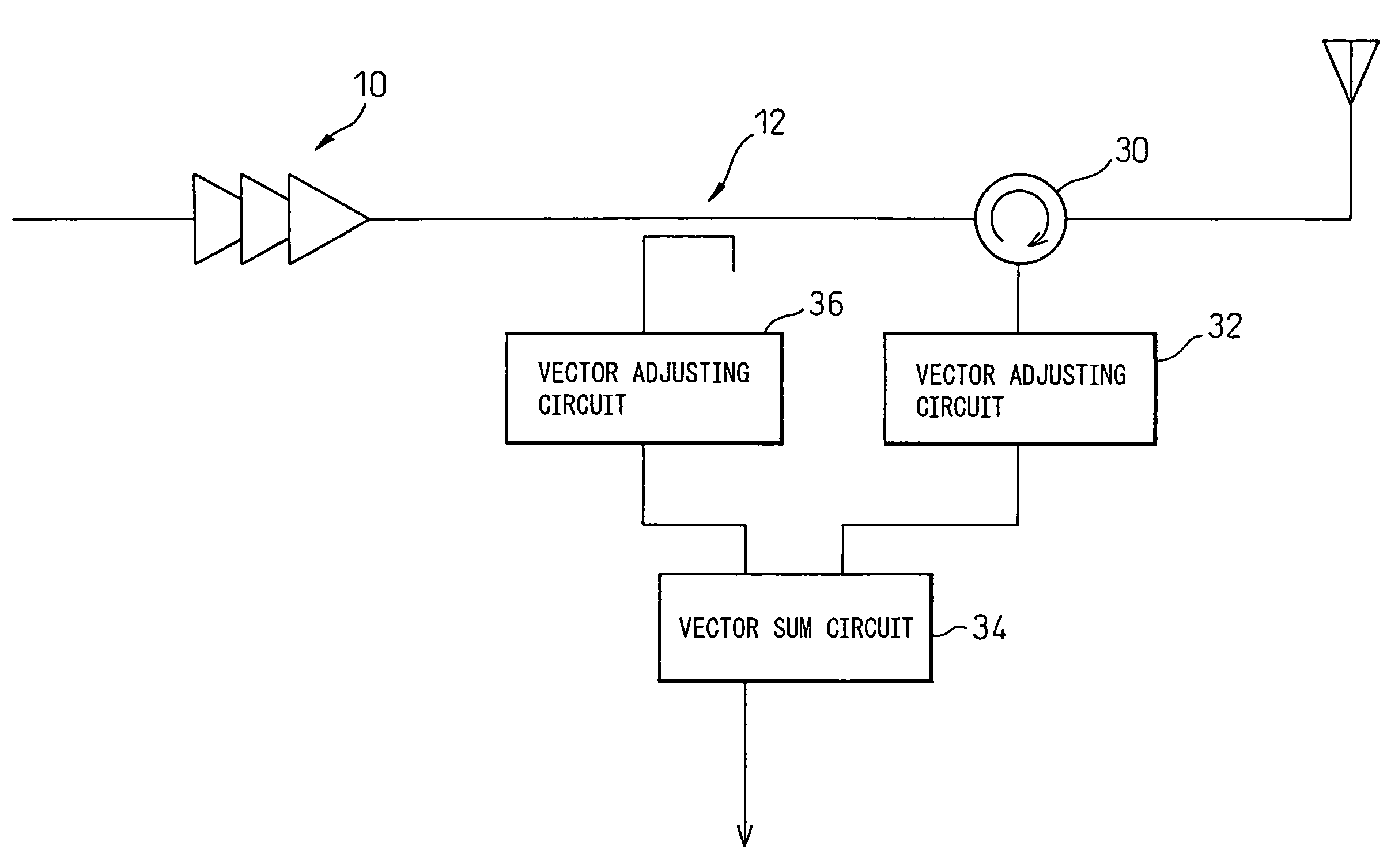
[0047]FIG. 8 shows the configuration of one example of a signal extraction circuit according to one embodiment of the present invention. The same component elements as those in FIG. 5 are designated by the same reference numerals. Isolator 14 in FIG. 7 is replaced by circulator 30 for extracting a reflected signal.

[0048]Among the signal components reflected from the connecting portion 22 of the antenna 13 and leaking into the feedback signal (20), the dominant one is, as earlier described, the component that is passed through the directional coupler 12, reflected at the output end of the transistor 10, and is separated by the directional coupler 12, and the next dominant one is the component that directly leaks into the feedback signal in the directional coupler 12; there could also be other components leaking into the feedback signal (20) through many different paths. However, the sum of these components can be expressed by a single vector having a certain amplitude and phase.

[0049...


PUM


Abstract

To cancel a reflected wave reflected from a connecting portion (22) and leaking into a feedback signal when a non-matched component is connected, the reflected wave is extracted by a circulator (30) and its phase and amplitude are adjusted by a vector adjusting circuit (32), and then the thus adjusted reflected wave is vector-summed with the feedback signal in a vector sum circuit (34).

Description

CROSS-REFERENCE TO RELATED APPLICATIONS[0001]This is a continuation of International Application PCT / JP2004 / 017799, published in Japanese, with an international filing date of Nov. 30, 2004.TECHNICAL FIELD[0002]The present invention relates to a signal extraction circuit for extracting a portion of a signal, and a distortion-compensated amplifier incorporating such a signal extraction circuit; more particularly, the invention relates to a signal extraction circuit suitable for use in a distortion-compensated amplifier in which a digital predistortion technique is employed, and also relates to a distortion-compensated amplifier incorporating such a signal extraction circuit.BACKGROUND ART[0003]In recent years, high-efficiency transmissions based on digital techniques have come to be used widely in wireless communications. When using a multilevel phase modulation scheme in wireless communications, it is important to employ a technique for linearizing transmitter amplifier characterist...

Claims


Application Information

Patent Timeline
Patent Type & Authority Patents(United States)
IPC IPC(8): H03F1/26
CPCH03F1/32H03F1/3247H03F1/3282H03F1/3294H03F3/24H04B1/0475H03F2200/204H03F2200/207H03F2200/336H03F2200/451H03F2201/3227H03F2201/3231
Inventor OKAZAKI, YOUSUKEMAEDA, HIROAKISEINO, YASUSHIONO, TAKASHI
Owner FUJITSU LTD
Why Eureka
Try Eureka