Vehicle exhaust apparatus and motorcycle equipped therewith

a technology for exhaust apparatuses and motorcycles, which is applied in exhaust treatment, gas passages, combustion engines, etc., can solve the problems of riding sensation, uncomfortable operation, and temporary loss of engine power, and achieve the effect of eliminating torque valley, rapid response, and improving operation feeling

Active Publication Date: 2008-12-02
KAWASAKI MOTORS LTD
View PDF9 Cites 12 Cited by
  • Summary
  • Abstract
  • Description
  • Claims
  • Application Information

AI Technical Summary

Benefits of technology

[0010]In view of the foregoing, an object of the present invention is to enable smooth acceleration during acceleration in a low-speed range of the engine by following an acceleration operation by an operator of a vehicle without temporarily decreasing the engine torque, i.e., without generating a torque valley of the engine torque, and thereby maintaining a good operational feeling during acceleration.
[0012]Since the expansion chamber whose inner peripheral surface is formed in the arc shape is connected onto the exhaust gas downstream side of the exhaust collector portion as in the above configuration, exhaust gases of the engine are collected in the exhaust collector portion from the plural exhaust pipes and then, flows into the expansion chamber immediately after the exhaust gases are collected or pass through a short distance in the exhaust collector portion, the mutual inference of the exhaust gases is decreased and the generation of large back pressure is prevented. Therefore, the exhaust gas can smoothly flow through the exhaust passage and the generation of the torque valley in the low-speed range of the engine can be eliminated. That is, during acceleration in the low-speed range, the acceleration of the engine can be smoothly performed by following the acceleration operation by the operator without temporarily decreasing the torque, and thereby a good operation feeling can be maintained during the acceleration operation.
[0014]According to the above configuration, the whole of the exhaust gas collected in the exhaust collector portion from the plural exhaust passages flows rapidly and smoothly to the exhaust gas downstream side along the inner surface of the spherical expansion chamber, so that the effect of eliminating the torque valley can be improved.
[0016]According to the above configuration, the expansion chamber can easily be arranged even in a space where the size is restricted in the vertical direction like the lower space of the engine of the motorcycle.
[0022]In an acceleration operation of the motorcycle, generally a rider of the motorcycle grasps and rotates a throttle grip, and rapid response (sense of unity) of the vehicle movement is required corresponding to the operation. Therefore, by providing the above-described vehicle exhaust apparatus to the motorcycle, the operation feeling is further improved by eliminating the torque valley during acceleration in the low-speed range of the engine. The compactness of the exhaust apparatus can also be maintained.

Problems solved by technology

This phenomenon gives a rider a feeling that power of the engine is temporarily lost.
That is, during the acceleration operation, because the torque is temporarily decreased against the rider's operation of accelerating, the operation does not feel comfortable.
However, the expanded collector portion has little effect of eliminating the torque valley in the low-speed range.

Method used


Image

  • Vehicle exhaust apparatus and motorcycle equipped therewith
  • Vehicle exhaust apparatus and motorcycle equipped therewith
  • Vehicle exhaust apparatus and motorcycle equipped therewith

Examples


first embodiment

[0042]A first embodiment of the present invention will be described below with reference to FIGS. 1 to 9.

(Schematic Configuration of Entire Motorcycle)

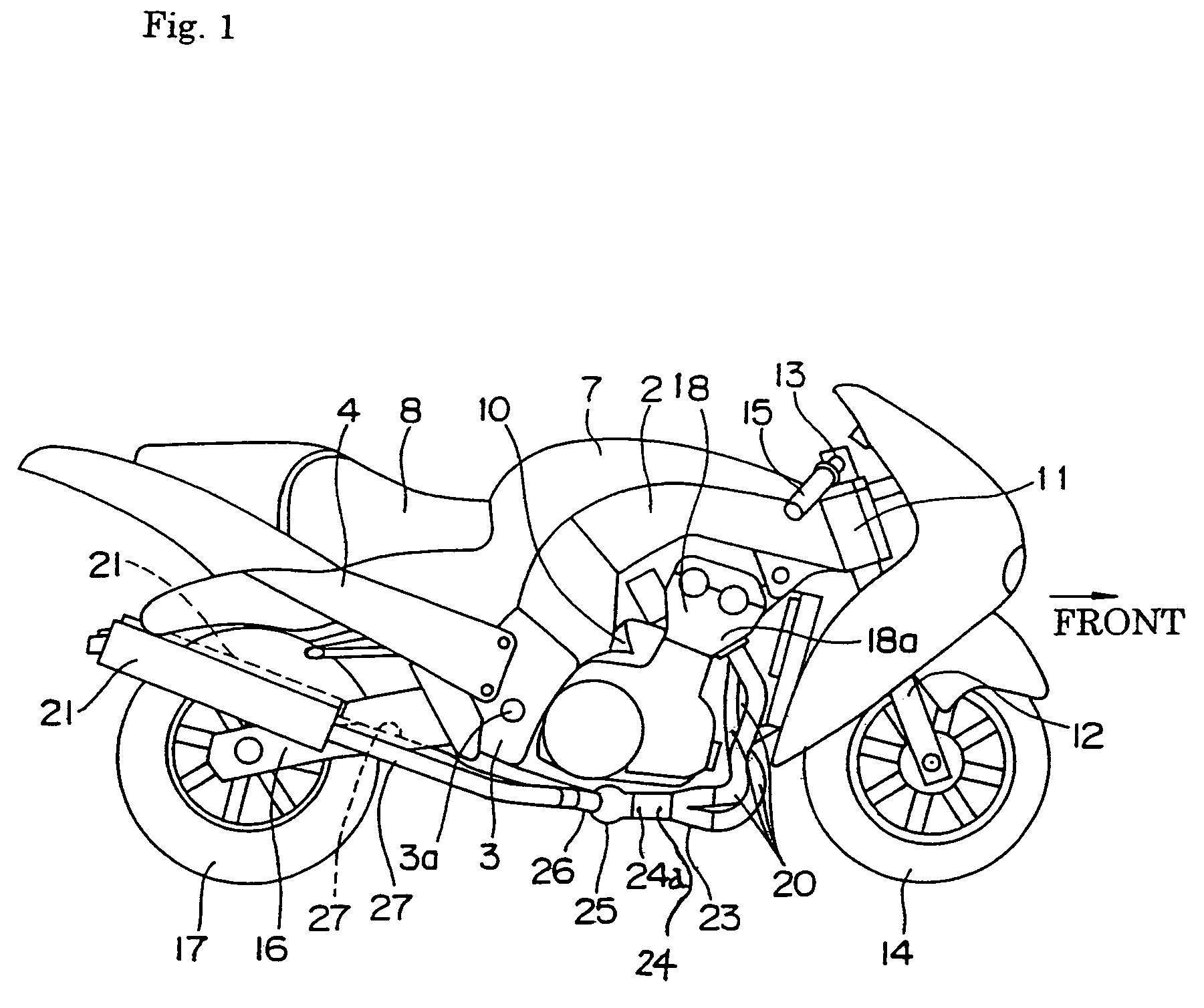
[0043]FIG. 1 is a right side view (side view on the right side of a rider) showing a motorcycle equipped with an exhaust apparatus according to the present invention. Referring to FIG. 1, a body frame includes mainly right and left main frames 2, right and left swinging arm brackets 3, and a rear frame 4. The swinging arm brackets 3 are formed at rear lower-end portions of the main frames 2. The rear frame 4 is extended behind and upward from the swinging arm brackets 3. A fuel tank 7, a seat 8, and the like are provided on the body frames 2, and a multi-cylinder engine 10 is mounted in a lower space of the main frames 2. A front fork 12 is supported in a head pipe 11 formed at the front end of the main frames 2, a handle 13 is provided in an upper end portion of the front fork 12 through the bracket or the like, and a front wheel 14 ...

second embodiment

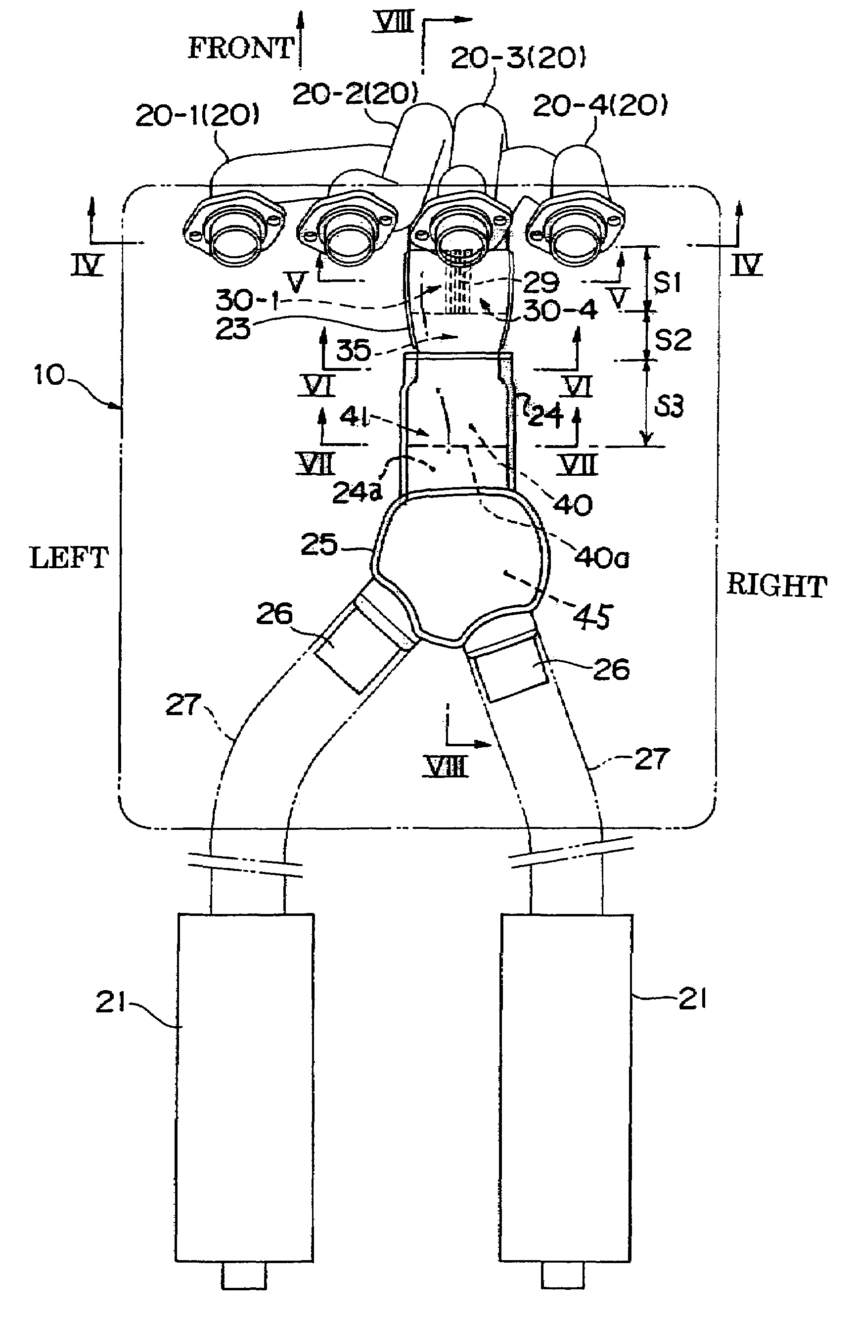
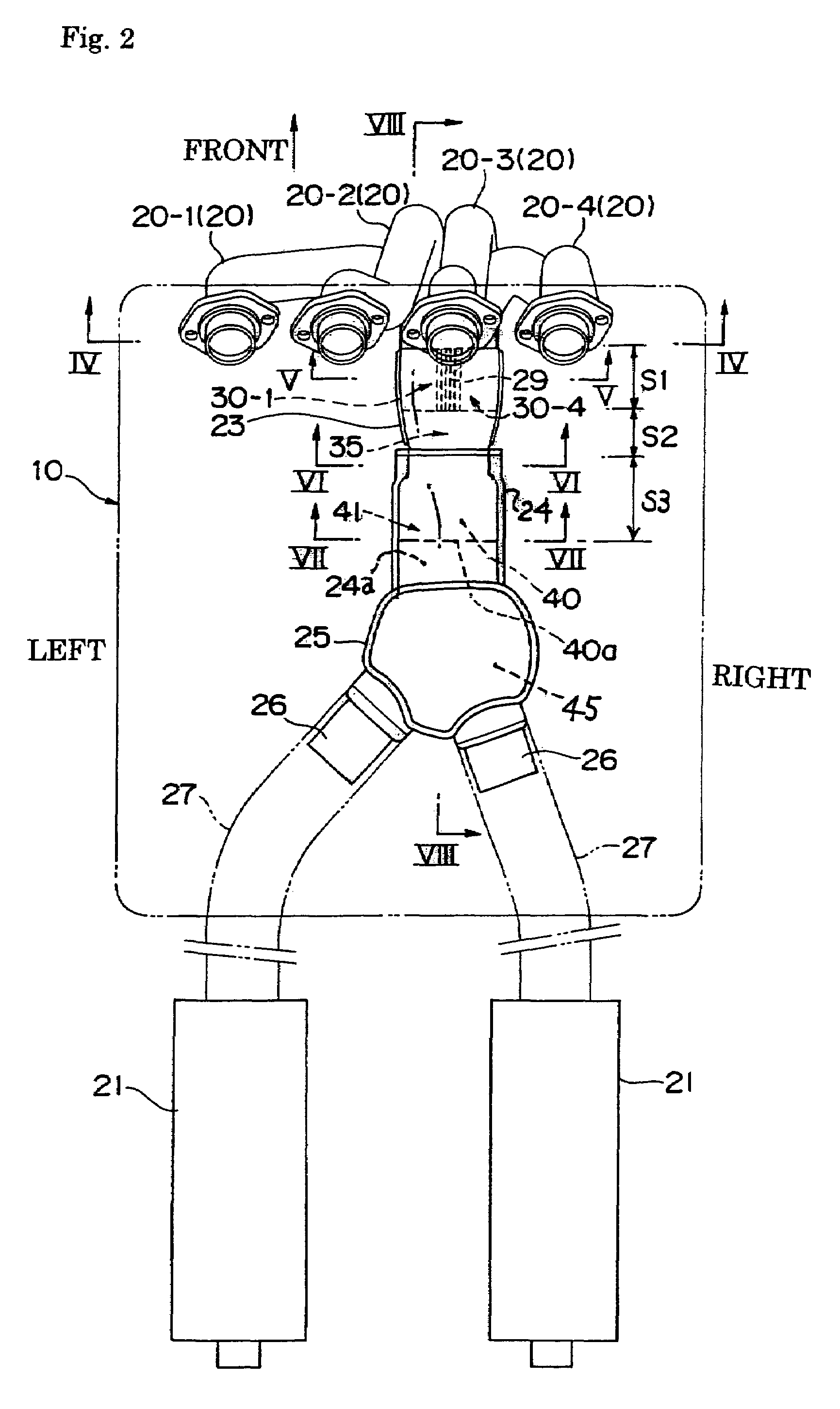
[0062]FIGS. 10 to 13 show a second embodiment of the present invention. Referring to FIG. 10, which shows a plan view of an exhaust apparatus, the exhaust apparatus of the second embodiment has the basic structure similar to that of the first embodiment. The exhaust apparatus of the second embodiment includes the four individual cylinder exhaust pipes 20-1, 20-2, 20-3, and 20-4, the upper and lower of first exhaust collector pipes 23, the second exhaust collector pipe 24, the expansion pipe 25, the right and left branched exhaust pipes 26, the right and left rear exhaust pipes 27, and the right and left exhaust mufflers 21 in the order from the exhaust gas upstream side. The first exhaust collector pipes 23 are arranged below the engine 10. The second exhaust collector pipe 24 is connected to rear ends of the first exhaust collector pipes 23. The expansion pipe 25 is connected to the rear end of the second exhaust collector pipe 24. The branched exhaust pipes 26 are connected to the...

third embodiment

[0070]FIG. 14 shows a third embodiment of the present invention, and shows a horizontal section (corresponding to FIG. 9) near the first and second exhaust collector pipes 23 and 24. Referring to FIG. 14, the exhaust apparatus includes the four individual cylinder exhaust pipes 20-1, 20-2, 20-3, and 20-4, the upper and lower first exhaust collector pipes 23, the second exhaust collector pipe 24, and the expansion chamber 45 in the order from the exhaust gas upstream side. The substantially spherical expansion chamber 45 is connected to the rear side of the second exhaust collector portion 24a in the rear half portion of the second exhaust collector pipe 24. These structures of the third embodiment are similar to those of the first embodiment. However, in the third embodiment, only one exhaust muffler 21 is connected to the rear portion of the expansion pipe 25 through only one rear exhaust pipe 27. In the third embodiment, the same components as in the first embodiment are designate...


PUM


Abstract

In a vehicle exhaust apparatus constituting an exhaust passage to an exhaust muffler from a plurality of exhaust pipes connected to a multi-cylinder engine, an expansion chamber is formed along the exhaust passage and is connected to an exhaust collector portion. The expansion chamber is formed so as to expand outward from the exhaust collector portion in a substantially arc or chevron shape when viewed from a direction substantially orthogonal to an exhaust gasflow. Preferably, the expansion chamber is formed in a spherical shape and plural branched exhaust pipes are formed on the exhaust gas downstream side of the expansion chamber.

Description

BACKGROUND OF THE INVENTION[0001]1. Field of the Invention[0002]The present invention relates to a vehicle exhaust apparatus and a motorcycle equipped therewith, particularly to the vehicle exhaust apparatus constituting an exhaust passage to an exhaust muffler from plural exhaust pipes connected to a multi-cylinder engine, and the motorcycle equipped with the vehicle exhaust apparatus.[0003]2. Description of the Related Art[0004]Some vehicle exhaust apparatuses connected to a multi-cylinder engine have a structure in which individual cylinder exhaust pipes connected to cylinders are independently connected to respective exhaust mufflers. From the standpoint of compact piping space and exhaust gas pulsation attenuation, frequently the vehicle exhaust apparatus has a structure in which plural exhaust passages are collected at the midpoint of an exhaust passage or a structure in which the exhaust passage is rebranched into plural exhaust passages after they are collected.[0005]FIGS. 1...

Claims


Application Information

Patent Timeline
Patent Type & Authority Patents(United States)
IPC IPC(8): F01N7/10F01N13/04F01N13/08F01N13/10
CPCF01N13/08F01N2260/06F01N2470/00F01N2590/04F02B27/04
Inventor KIKUCHI, HIROYUKIYOKOYAMA, NAOKI
Owner KAWASAKI MOTORS LTD
Why Eureka
Try Eureka