Laser triangulation system

a laser triangulation and laser technology, applied in the field of laser triangulation systems, can solve the problems of system resolution and accuracy degrading in an indeterminate manner, mechanical complexity, and lack of incident laser power

Active Publication Date: 2008-12-02
3DM DEVICES
View PDF16 Cites 40 Cited by
  • Summary
  • Abstract
  • Description
  • Claims
  • Application Information

AI Technical Summary

Problems solved by technology

The first, dynamic system, has the advantage of high incident laser power in a single spot, but suffers form mechanical complexity, whereas the seconds static configuration, has no moving parts but can suffer from lack of incident laser power as the beam is spread over a long line and the inability to dynamically modify the intensity of laser power along the laser line.
However, if one or more of these conditions are not met, then system resolution and accuracy start to degrade in an indeterminate manner.
The two dominant dynamic conditions that affect system performance are the presence of clipping of the peak and inadequate signal amplitude above the background.
Fast response control circuits are required and there will always be some residual step response error if the surface exhibits abrupt reflectance or range changes.
In contrast, a static laser triangulation system has a basic limitation in that the intensity of the laser cannot be varied along the line length, only temporally for the whole line from scan to scan.
It is thus impossible to provide optimum exposure conditions for many real objects at all points along the line and compromises or multiple exposures are required.
To our knowledge, current system designs do not address this issue.
There are discussions about optimising system setup for best response, minimising spot size to avoid the effect of reflectance changes, providing large dynamic response detectors and post processing of Point Cloud data to remove outliers and erroneous data points, but no attempt to address the fundamental exposure problem.

Method used


Image

  • Laser triangulation system
  • Laser triangulation system
  • Laser triangulation system

Examples


Embodiment Construction

Quality Factors

[0103]The quality factors attached to each centroid value provide cues to alert a user that the data may be suspect.

[0104]The quality factors are determined as follows.[0105]In the calculation phase on each video line, extra data is available to describe the ‘quality’ of the centroid pulse.[0106]In its simplest form, this is just whether the pulse height is within acceptable levels.[0107]Other centroid quality information can include pulse width at the base or half height, total power in the pulse, or the degree of symmetry present in the pulse.[0108]More advanced quality calculations can look at adjacent video lines and provide the degree of correlation to centroids in the ‘y’ direction, or identify more than one candidate centroid on the same line and report these as secondary choices.

[0109]The simple quality factors can be encoded in spare bits in the 16 bit centroid data, but the more advanced factors require the addition of an extra byte (S bits).

[0110]The qualit...


PUM


Abstract

A method for measuring the range to multiple points on a surface by projecting a line of light onto the surface, imaging said line of light onto a photodetector, computing the centroid of said line of light, computing quality factors for each computed centroid and encoding the quality factors as one or more bits in the centroid value, transmitting said centroid value to a data receiver, and computing the range to the surface for each point corresponding to each centroid value.

Description

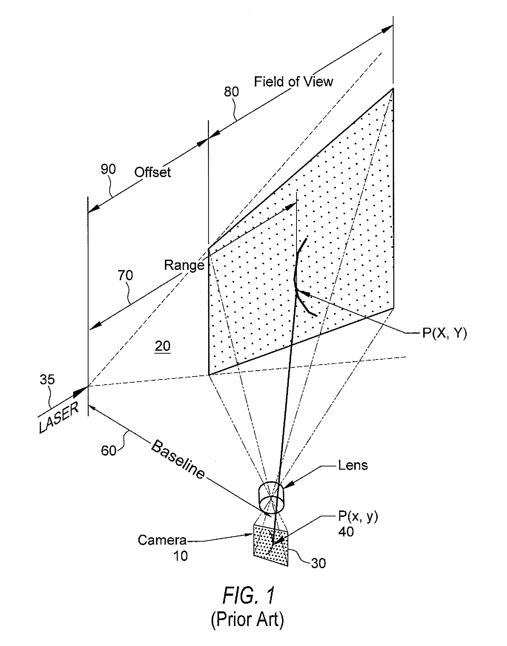
RELATED APPLICATION[0001]This application claims the benefit of previously filed Oct. 24, 2003, Provisional Patent Application No. 60 / 513,554.FIELD OF THE INVENTION[0002]The present invention relates to techniques to improve the quality of measurements made with laser triangulation sensors.[0003]The first technique adds quality factors to each data point at the time of acquisition and uses these quality factors to adjust real time operating settings. These quality factors can also be used in later processing operations to select high quality data from the complete data set.BACKGROUND OF THE INVENTION[0004]A laser triangulation sensor provides dimensional information about an object placed in the path of a sheet of laser light.[0005]Referring to FIG. 1, a camera 10 placed at an oblique angle to the sheet of light 20 formed from laser 25 acquires an image 30 showing the location of the laser line on the surface of the object. In a calibrated system the location of a point x, y 40 in t...

Claims


Application Information

Patent Timeline
Patent Type & Authority Patents(United States)
IPC IPC(8): G01B11/24G01B11/25G01S17/48
CPCG01B11/25G01S17/48
Inventor KEIGHTLEY, JOHNCUNHA, ADRIANO
Owner 3DM DEVICES
Why Eureka
Try Eureka