Method and apparatus for forming by electrochemical material removal

a technology of electrochemical material removal and rotor wheel, which is applied in the direction of manufacturing tools, electrode vibration holders, electric circuits machining, etc., can solve the problems of rotor wheel repair, extremely cost and time-consuming methods, and unsuitable flank contact geometry of these blades, etc., and achieve the effect of low effor

Inactive Publication Date: 2008-12-09
ROLLS ROYCE DEUT LTD & CO KG
View PDF20 Cites 21 Cited by
  • Summary
  • Abstract
  • Description
  • Claims
  • Application Information

AI Technical Summary

Benefits of technology

[0007]The present invention, in a broad aspect, provides for a method for the electrochemical machining of workpieces which also enables components of complex shape, in particular one-piece turbomachine rotor wheels with curved blades made from a solid, to be produced and repaired with low effort, and for the development of an appropriate apparatus for the performance of said method.
[0009]The principle underlying the method for electrochemical machining of workpieces in accordance with the present invention is that the electrode or the workpiece perform a circular oscillation synchronously with their linear oscillation, enabling a complexly contoured electrode, for example in the shape of a three-dimensionally curved compressor blade, to virtually turn into the workpiece with minimum material removal. The further forming process until the precise space width and blade shape are obtained is then performed without linear oscillation, merely by subsequent circular oscillation in combination with circular feed in the one and / or the other direction of rotation. Thus, complexly shaped items, such as integral, three-dimensionally curved blades and, accordingly, one-piece turbine wheels (so-called blisks) can be produced or repaired by electrochemical machining with maximum precision and surface finish and free from material stress, obviating any further processing to smoothen the surface as is necessary with the known processes for the production of blisks, and significantly reducing manufacturing and repair cost.

Problems solved by technology

Due to the heavy curvature of these blades and the complex shape of the space between the blades, the geometries of these blades are unsuitable for production in flank contact.
However, this method is extremely cost and time-consuming and, therefore, lends itself only to a limited extent to the series-production of, for example, compressor disks in blisk technology.
Also, the repair of a rotor wheel, where damaged blades or blade sections are to be replaced or corrected by mold welding, build-up welding or the like, requires costly re-machining of the item under repair by a cutting process.
The apparatus described therein is, however, unsuitable for the production of one-piece rotor wheels where the blades are machined from a solid, for example blisk-technology rotor wheels, since it does not provide for the complex, three-dimensionally curved contour of the space to be produced between adjacent blades.

Method used


Image

  • Method and apparatus for forming by electrochemical material removal
  • Method and apparatus for forming by electrochemical material removal
  • Method and apparatus for forming by electrochemical material removal

Examples


Embodiment Construction

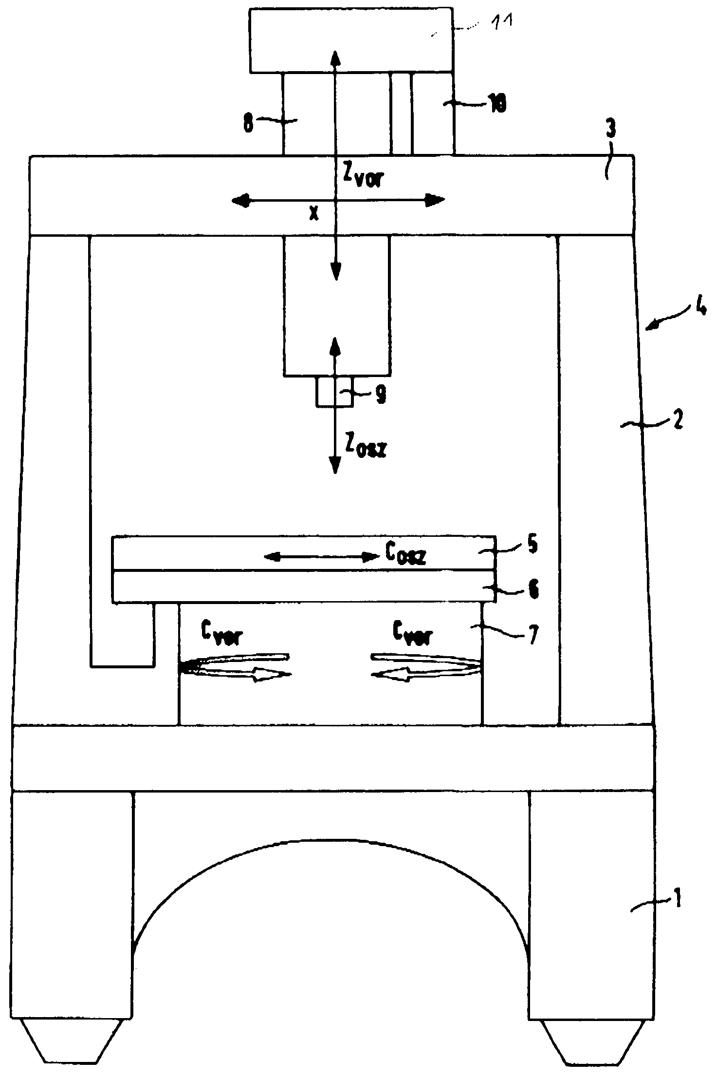
[0018]The apparatus according to FIG. 9 comprises a machine casing 4 consisting of a base 1, side members 2 and a gantry 3. The base 1 carries a workpiece holder 5, i.e. a work table, which holds the workpiece (not shown) to be processed. The work table / workpiece holder 5 is connected to a rotary-oscillation drive 6 (first drive) in order to set the work table 5 and, thus, the workpiece to be machined in circular oscillation (arrow Cosz) around a vertical center axis. A rotary-feed drive 7 (second drive), which is connected to the rotary-oscillation drive 6, provides a linear horizontal circular feed (arrow Cvor) of the workpiece holder 5 in either direction simultaneously with the circular oscillation.

[0019]A tool slide 8 with electrode holder 9 is arranged on the machine gantry 3 and is transversable in the direction of the double arrow X. The electrode holder 9, which is linearly moveable in the tool slide 8, is capable of performing a linear oscillation (double arrow Zosz) and a...


PUM

PropertyMeasurementUnit
electrochemicalaaaaaaaaaa
shapesaaaaaaaaaa
shapeaaaaaaaaaa

Abstract

When forming metallic components, in particular three-dimensionally curved blades, which constitute a single piece with the blading of turbomachine rotor wheels, the linear oscillation of the electrode acting as a tool is superimposed by a circular oscillation, enabling the electrode to turn into the workpiece conformally with its shape. Further forming is performed by circular oscillation with circular feed in the one and / or the other direction. An embodiment of the corresponding apparatus comprises an electrode holder (9) with linear feed (Zvor) and linear oscillation (Zosz) and a workpiece holder (5) with circular oscillation (Cosz) and circular feed (Cvor).

Description

[0001]This application claims priority to German Patent Application DE10258920.8 filed Dec. 17, 2002, the entirety of which is incorporated by reference herein.BACKGROUND OF THE INVENTION[0002]This invention relates to a method and apparatus for the forming of components of complex shape, in particular turbomachine rotor wheels, which constitute a single piece with the blading, by electrochemical material removal.[0003]As is known, the complex, three-dimensionally curved contours of blades of one-piece rotor wheels for fans, compressors and turbines made from a solid, for example the blisk-technology rotor wheels of jet engines, are produced by milling the solid with a cutting tool. Due to the heavy curvature of these blades and the complex shape of the space between the blades, the geometries of these blades are unsuitable for production in flank contact. The only way to produce these shapes is machining in point contact. However, this method is extremely cost and time-consuming an...

Claims


Application Information

Patent Timeline
Patent Type & Authority Patents(United States)
IPC IPC(8): B23H3/04B23H9/10C25D17/00B23H3/00B23H7/28
CPCB23H3/00B23H7/28B23H9/10B23H3/04
Inventor MIELKE, RAINER
Owner ROLLS ROYCE DEUT LTD & CO KG
Why Eureka
Try Eureka