Motor controlling method, motor controlling apparatus, and recording apparatus

a technology of motor control and recording apparatus, applied in the direction of electric controllers, dynamo-electric converter control, instruments, etc., can solve the problems of increasing the size and cost of the printer, not practicable, and applying this method

Active Publication Date: 2008-12-09
BROTHER KOGYO KK
View PDF14 Cites 6 Cited by
  • Summary
  • Abstract
  • Description
  • Claims
  • Application Information

AI Technical Summary

Benefits of technology

[0018]More specifically explained, in the disclosed method, the employment of the disconnecting device is needed for the purpose of changing adaptively the control parameter. In addition, use of special signals is needed for the purpose of identifying the rotary portion and the moving apparatus. These special features lead to increasing the size and cost of the printer.
[0021]In the above-described technical background, the present invention has been developed. It is therefore an object of the present invention to solve at least one of the above-indicated problems. It is another object of the present invention to provide the art of adjusting, even in the case where an operating apparatus operates under each one of a plurality of operating conditions, a control parameter to an appropriate value corresponding to the each operating condition, while an electric motor as a drive source of the operating apparatus is operated, so that the motor can be appropriately controlled under the each operating condition.
[0033]The present recording apparatus employs the two adjustable parameters corresponding to the two directions in which the carriage is driven or moved. Thus, each of the two adjustable parameters corresponding to the two directions can be adjusted to an appropriate value, and accordingly the carriage can be driven in an appropriate manner. Therefore, the present recording apparatus can continue to record excellent images on recording media.

Problems solved by technology

However, it is difficult, and is not practical, to apply this method to the adjustment of the control parameter when the carriage is moved in the different directions.
These special features lead to increasing the size and cost of the printer.

Method used


Image

  • Motor controlling method, motor controlling apparatus, and recording apparatus
  • Motor controlling method, motor controlling apparatus, and recording apparatus
  • Motor controlling method, motor controlling apparatus, and recording apparatus

Examples


first embodiment

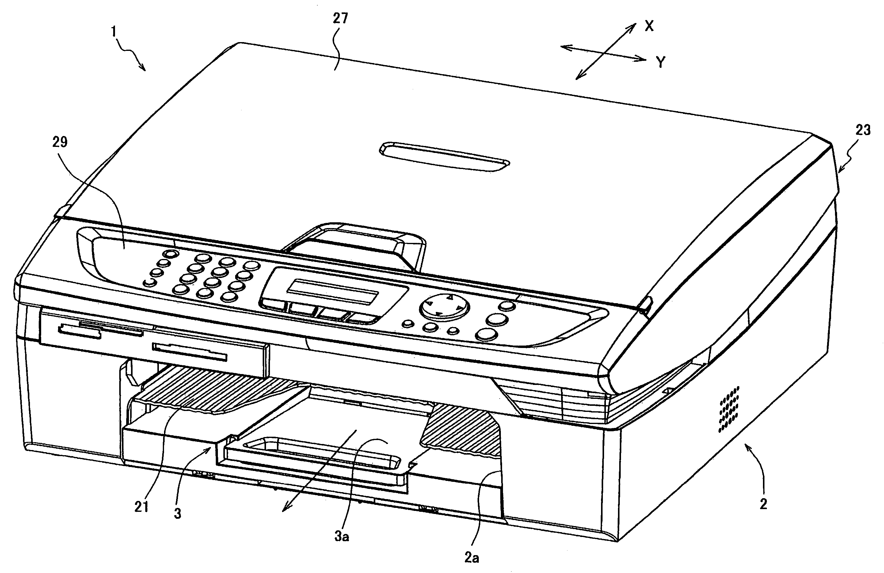
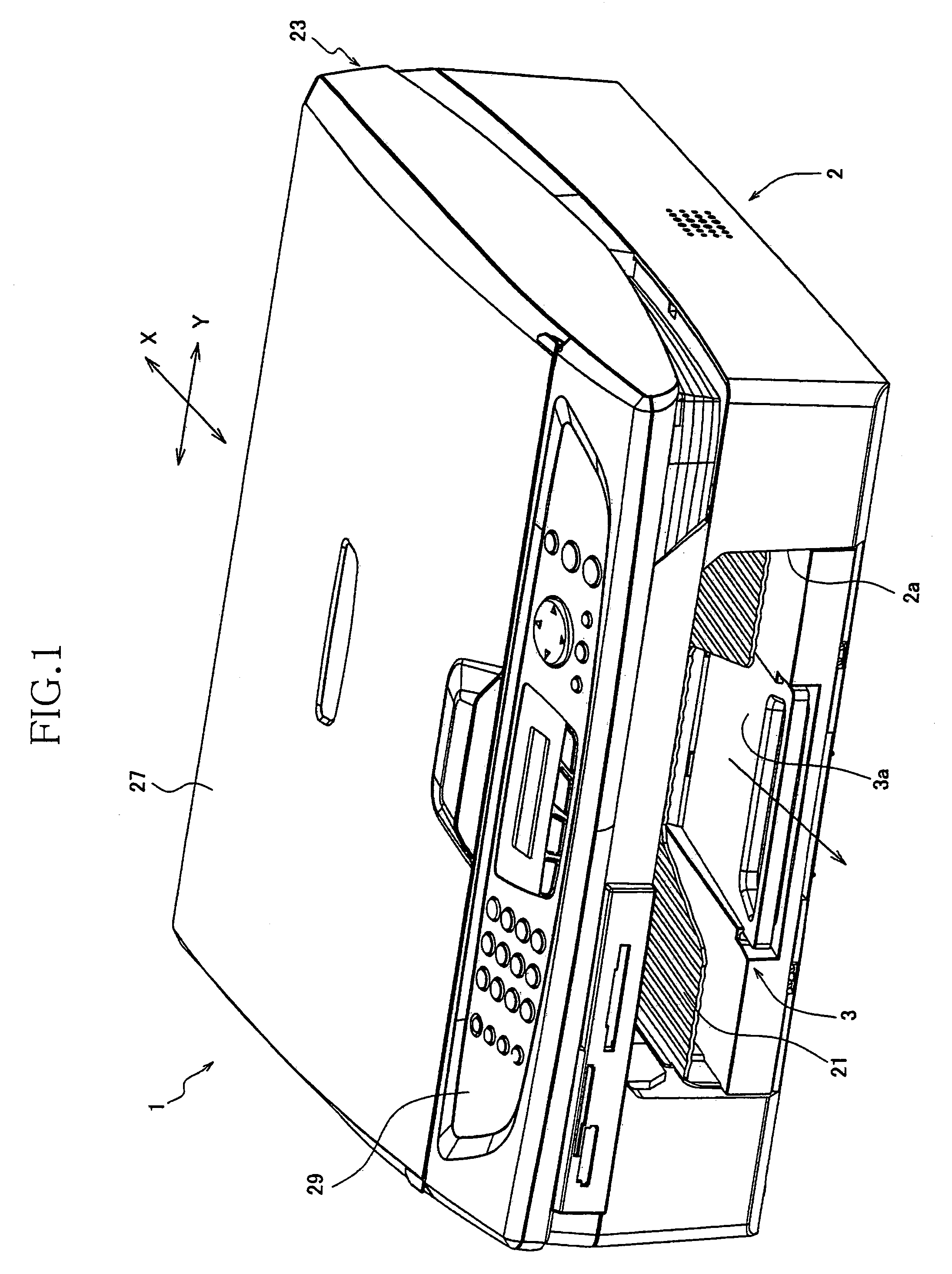
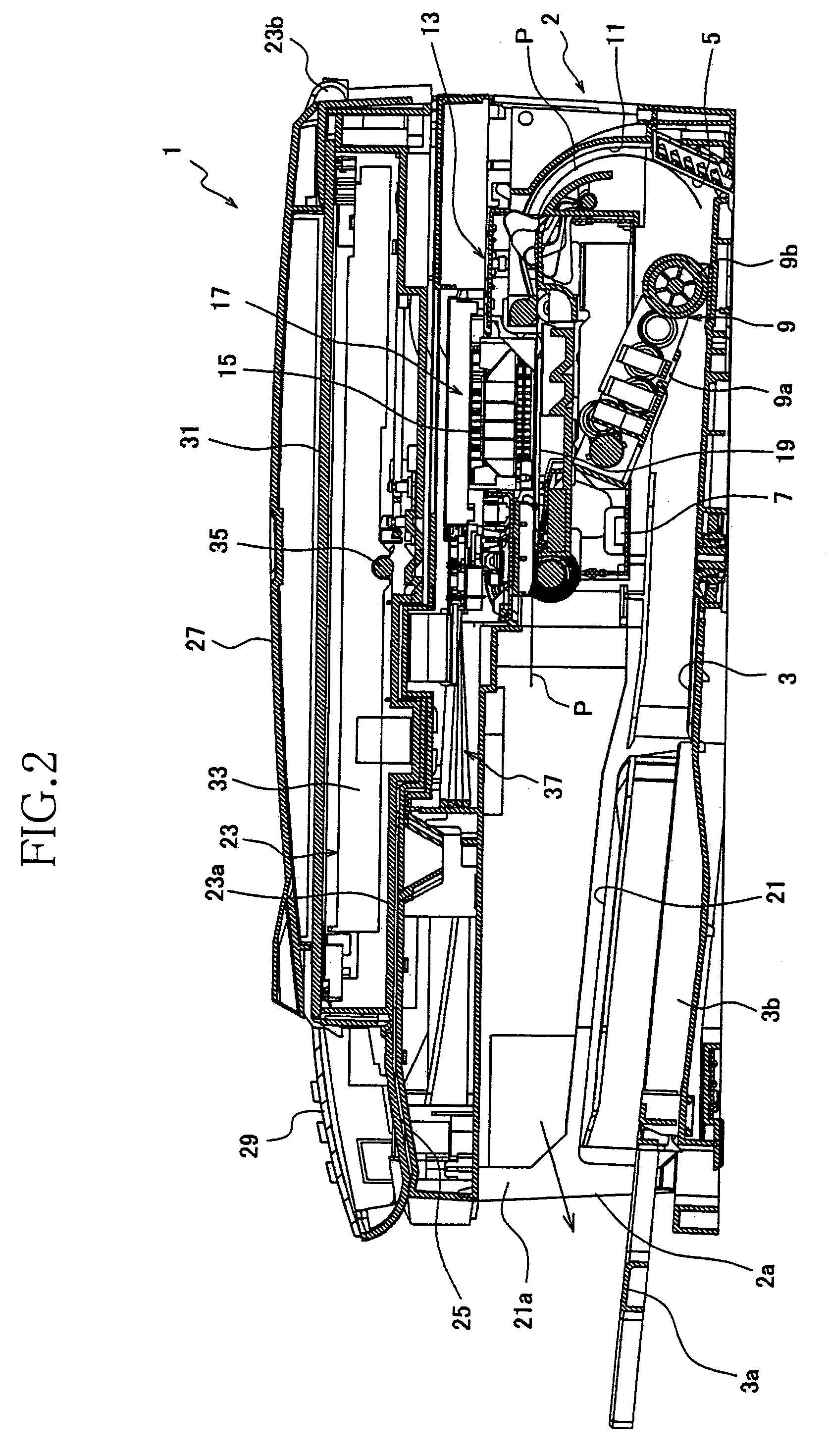
[0058]FIGS. 1 and 2 show a multiple-function device (MFD) 1 to which the present invention is applied. The MFD 1 has a printer function, a copier function, a scanner function, and a facsimile-machine function. The MFD 1 includes a housing 2 formed of a synthetic resin; and a sheet cassette 3 that is insertable into a bottom portion of the housing 2 via a front opening 2a thereof.

[0059]The sheet cassette 3 has a construction assuring that the cassette 3 can accommodate a plurality of cut sheets, P, such as A4-size sheets or legal-size sheets, each as a recording medium, such that the cut sheets P are stacked on each other and respective short sides of the sheets P extend in a direction (i.e., a main scan direction or a Y direction) perpendicular to a sheet-feed direction (i.e., a sub-scan direction or an X direction).

[0060]The sheet cassette 3 includes an auxiliary support member 3a that is provided in a front portion of the cassette 3, such that the auxiliary support member 3a is mo...

second embodiment

[0171]In the above-described first embodiment, the motor controlling method and apparatus in accordance with the present invention are applied to the CR motor 10 that drives or moves the carriage 17. However, those can also be applied to an electric motor that feeds a cut sheet P as a recording medium, in the MFD 1 shown in FIG. 1. In the second embodiment, the MFD 1 employs, as control parameters, a plurality of adjustable parameters β respectively corresponding to a plurality of sorts of cut sheets P as a plurality of recording media.

[0172]The MFD 1 includes a sheet feeding system as shown in FIG. 11. The sheet feeding system includes a sheet feeding portion (i.e., a sheet feeder) 40, and a sheet-feeding controlling device (FIG. 12). The same reference numerals as used in FIGS. 1 and 2 are used to designate the corresponding elements and parts of the second embodiment, and the description thereof is omitted.

[0173]The sheet feeding portion 40 includes a sheet cassette 3 that accomm...


PUM


Abstract

A method of controlling, by an adaptive control method, an electric motor as a drive source of an operating apparatus that operates, based on a driving force produced by the electric motor, under an arbitrary one of a plurality of operating conditions, and exhibits different dynamic characteristics corresponding to the plurality of operating conditions. The method includes preparing, for a control portion controlling the electric motor, a plurality of control-parameter groups which correspond to the plurality of operating conditions, respectively, and each group of which includes at least one control parameter comprising at least one adjustable parameter, determining, based on one of the control-parameter groups that corresponds to the arbitrary one of the operating conditions, and a plurality of target control outputs of the operating apparatus that correspond to a plurality of times, respectively, a plurality of control inputs to be inputted to the electric motor at the plurality of times, respectively, and adjusting, while the operating apparatus operates under one of the operating conditions that corresponds to each one of the control-parameter groups, the at least one adjustable parameter of the each control-parameter group in a direction in which an actual control-output trajectory including a plurality of actual control outputs of the operating apparatus that correspond to the plurality of control inputs, respectively, approaches a target control-output trajectory including the plurality of target control outputs of the operating apparatus.

Description

[0001]The present application is based on Japanese Patent Application No. 2005-191947 filed on Jun. 30, 2005, the contents of which are incorporated herein by reference.BACKGROUND OF THE INVENTION[0002]1. Field of the Invention[0003]The present invention relates to a method of controlling an electric motor while adjusting at least one control parameter under each one of a plurality of operating conditions; a motor controlling apparatus for controlling an electric motor in this method; and a recording apparatus that includes a recording head, a carriage on which the recording head is mounted, and this motor controlling apparatus used to move the carriage.[0004]2. Discussion of Related Art[0005]There has conventionally been known a controlling system including a controller that obtains, using at least one control parameter, operating amounts each to be applied to an electric motor so as to operate it and thereby drive an object. In addition, there has conventionally been known a contr...

Claims


Application Information

Patent Timeline
Patent Type & Authority Patents(United States)
IPC IPC(8): H02P5/00H02P8/00B41J19/18B41J2/01H02P29/00
CPCB41J11/485B41J13/0009B41J19/202
Inventor AKIYAMA, SHIGEKI
Owner BROTHER KOGYO KK
Why Eureka
Try Eureka