Transmitter and transmission control method

a transmission control and transmitter technology, applied in the field of transmitters, can solve problems such as the decrement of transmission performance, and achieve the effect of effective peak suppression and peak reduction

Inactive Publication Date: 2008-12-09
NTT DOCOMO INC
View PDF2 Cites 71 Cited by
  • Summary
  • Abstract
  • Description
  • Claims
  • Application Information

AI Technical Summary

Benefits of technology

[0031]For this purpose, according to the present invention, a transmitter includes: a peak reducing part carrying out peak reduction processing; an OFDM signal generating part generating an OFDM signal from input information signal; a cyclic shifting part generating a signal obtained from cyclically shifting the OFDM signal; and an adding part adding the OFDM signal and the cyclically shifted signal together. In this configuration, peak suppression can be carried out Further, a shift amount determining part determining a shift amount based on at least one of the OFDM signal and an output signal of the adding part may be provided, wherein: the cyclic shifting part may generate the signal cyclically shifted from the OFDM signal based on the shift amount determined by the shift amount determining part. In this configuration, the shift amount can be controlled, and thus, it is possible to achieve PARR reduction more effectively.
[0060]Thus, according to embodiments of the present invention described below, it is possible to provide the transmitter and the transmission control method by which peak reduction can be achieved without the necessity of transmitting a control signal concerning the peak reduction processing.

Problems solved by technology

However, the following problems may occur in the above-described background arts:
That is, in a case where the clipping (+filtering) is applied to reduce the PAPR, orthogonality among the subcarriers may not be kept, inter-subcarrier interference may occur, and thus, transmission performance may degrade.

Method used


Image

  • Transmitter and transmission control method
  • Transmitter and transmission control method
  • Transmitter and transmission control method

Examples


first embodiment

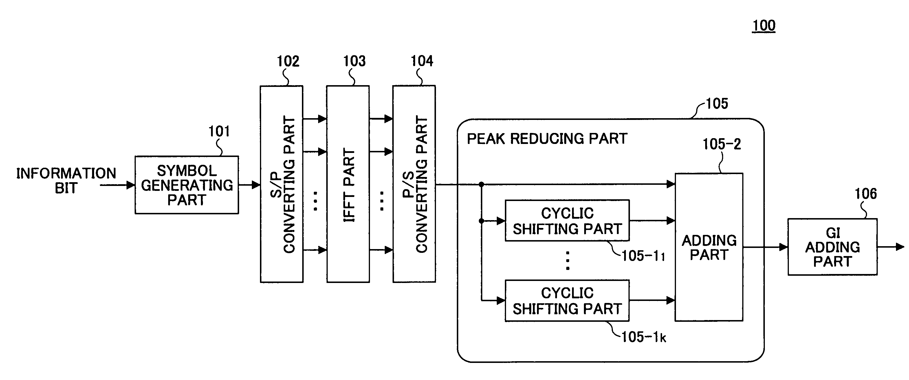
[0079]With reference to FIG. 5, a transmitter according to the present invention is described.

[0080]The transmitter 100 in the first embodiment includes a symbol generating part 101 to which information bits are input; a S / P (serial / parallel) converting part 102 connected with the symbol generating part 101; an IFFT (inverse fast Fourier transform) part 103 connected to the S / P converting part 102; a P / S (parallel / serial) converting part 104 connected to the IFFT part 103; a peak reducing part 105 connected to the P / S converting part 104; and a GI adding part 106 connected to the peak reducing part 105. The peak reducing part 105 includes cyclic shifting parts 105-11 through 105-1k (k is an integer and k>0) and an adding part 105-2 connected to the P / S converting part 104. The cyclic shifting parts 105-11 through 105-1k are connected to the adding part 105-2, which is connected to the GI adding part 106.

[0081]The symbol generating part 101 carries out, on the input information bit s...

second embodiment

[0094]A transmitter according to the present invention is described now with reference to FIG. 6.

[0095]In the first embodiment described above, the shift amounts in the cyclic shifting parts are fixed. However, by adaptively controlling the shift amounts, it is possible to achieve PAPR reduction more effectively.

[0096]The transmitter 100 in the second embodiment is different in a configuration of the peak reducing part from that of the transmitter described above with reference to FIG. 5.

[0097]The peak reducing part 107 according to the second embodiment includes the cyclic shifting part 107-1 and an adding part 107-2 connected to the P / S converting part 104, and a shift amount control part 107-3 connected to the cyclic shifting part 107-1 and the adding part 107-2. The cyclic shifting part 107-1 is connected to the adding part 107-2, and the adding part 107-2 is connected to the GI adding part 106. Description is made below assuming that only the single cyclic shifting part is appl...

third embodiment

[0104]A transmitter according to the present invention is described with reference to FIG. 8.

[0105]The transmitter 100 according to the third embodiment is different from the transmitter described with reference to FIG. 5 in the configuration of the peak reducing part.

[0106]The peak reducing part 109 according to the third embodiment includes cyclic shifting parts 109-11 through 109-1k, a shift amount and coefficient determining part 109-2 and a multiplier 109-4 connected to the P / S converting part 104, multiplier 109-51 through 109-5kconnected to the cyclic shifting parts 109-11 through 109-1krespectively, and an adding part 109-3 connected to the multipliers 109-11 through 109-1k. The shift amount and coefficient determining part 109-2 is connected to the cyclic shifting parts 109-11 through 109-1k and the multipliers 109-51 through 109-1k, and the adding part 109-3 is connected to the GI adding part 106.

[0107]In the embodiment described above, only the shift amount is controlled....


PUM


Abstract

A transmitter has a peak reducing part carrying out peak reduction processing; an OFDM signal generating part generating an OFDM signal from an input information signal; a cyclic shifting part generating a signal obtained from cyclically shifting the OFDM signal; and an adding part adding the OFDM signal and the cyclically shifted signal together.

Description

BACKGROUND OF THE INVENTION[0001]1. Field of the Invention[0002]The present invention relates to a transmitter applied for radio communication, and a transmission control method therefor.[0003]2. Description of the Related Art[0004]An OFDM (orthogonal frequency division multiplexing) transmission system has taken attention as a system avoiding influence of inter-symbol interference, even in a multi-path transmission environment. FIG. 1 shows a configuration of a transmitter applied in the OFDM transmission system.[0005]A transmitter 1 shown includes a symbol generating part 2 to which information bits are input; a S / P (serial / parallel) converting part 3 connected with the symbol generating part 2; an IFFT (inverse fast Fourier transform) part 4 connected to the S / P converting part 3; a P / S (parallel / serial) converting part 5 connected to the IFFT part 4; a GI adding part 6 connected to the P / S converting part 5 and an antenna 7 connected to the GI adding part 6.[0006]When informatio...

Claims


Application Information

Patent Timeline
Patent Type & Authority Patents(United States)
IPC IPC(8): H04B1/02H04J11/00H04B1/04H04L27/26
CPCH04L5/0023H04L27/2602H04L27/2614H04L27/26035
Inventor FUJII, HIROMASASHEN, JIYUNASAI, TAKAHIROSUDA, HIROHITO
Owner NTT DOCOMO INC
Why Eureka
Try Eureka