
Time-interleaved A/D converter device

a converter device and time-interleave technology, applied in the direction of code conversion, transmission system, instruments, etc., can solve the problems of deteriorating the characteristic of sfdr (spurious free dynamic ratio), and achieve the effect of facilitating application to a/d converter circuits integrated on a semiconductor substra

Inactive Publication Date: 2008-12-16
NEC ELECTRONICS CORP
View PDF4 Cites 20 Cited by
  • Summary
  • Abstract
  • Description
  • Claims
  • Application Information

AI Technical Summary

Benefits of technology

"The present invention provides a time-interleaved A / D converter device that includes first and second A / D converter circuits receiving first and second clock signals having a predetermined phase relationship with each other. The device also includes a phase adjustment circuit that receives the outputs of the first and second A / D converter circuits and uses the first clock signal as reference to adjust the phases of the second clock signals. The device can calibrate the clock skew without adding analog circuits and can follow changes in clock skew caused by temperature, voltage, and deterioration of the A / D converter circuits. The device can also adjust the phase of the second clock signal based on the output sequence of the first A / D converter circuit and the interpolation value derived from the output sequence. The technical effects of the invention include improved accuracy and reliability of the A / D converter device and simplified design and calibration process."

Problems solved by technology

However, this method has a problem that when a phase difference between the clocks for the A / D converter circuits used in parallel is not accurate, a spurious may occur in an A / D converted output, thereby deteriorating an SFDR (Spurious Free Dynamic Ratio) characteristic (refer to Non-patent Document 1).

Method used


Image

  • Time-interleaved A/D converter device
  • Time-interleaved A/D converter device
  • Time-interleaved A/D converter device

Examples


Embodiment Construction

OF THE INVENTION

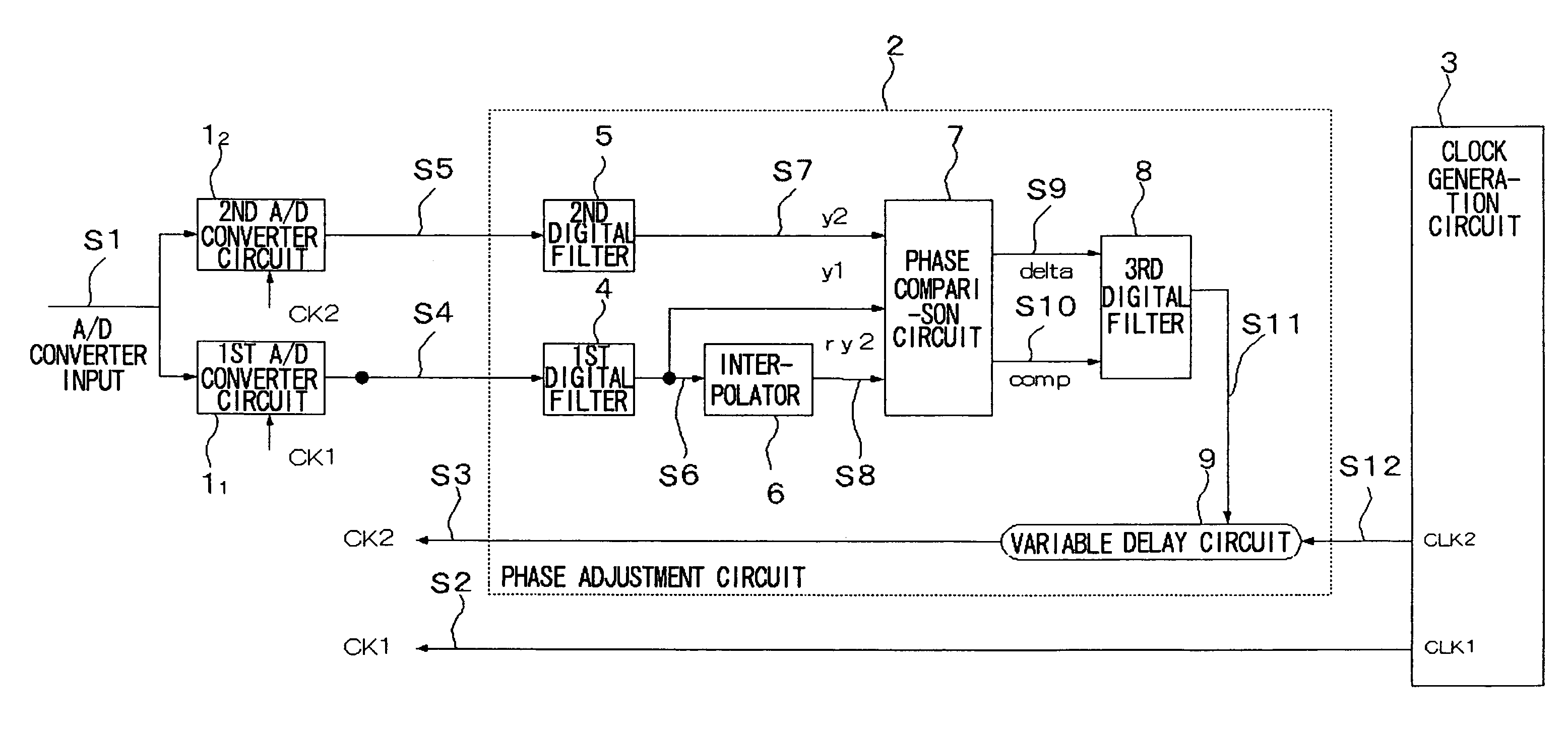
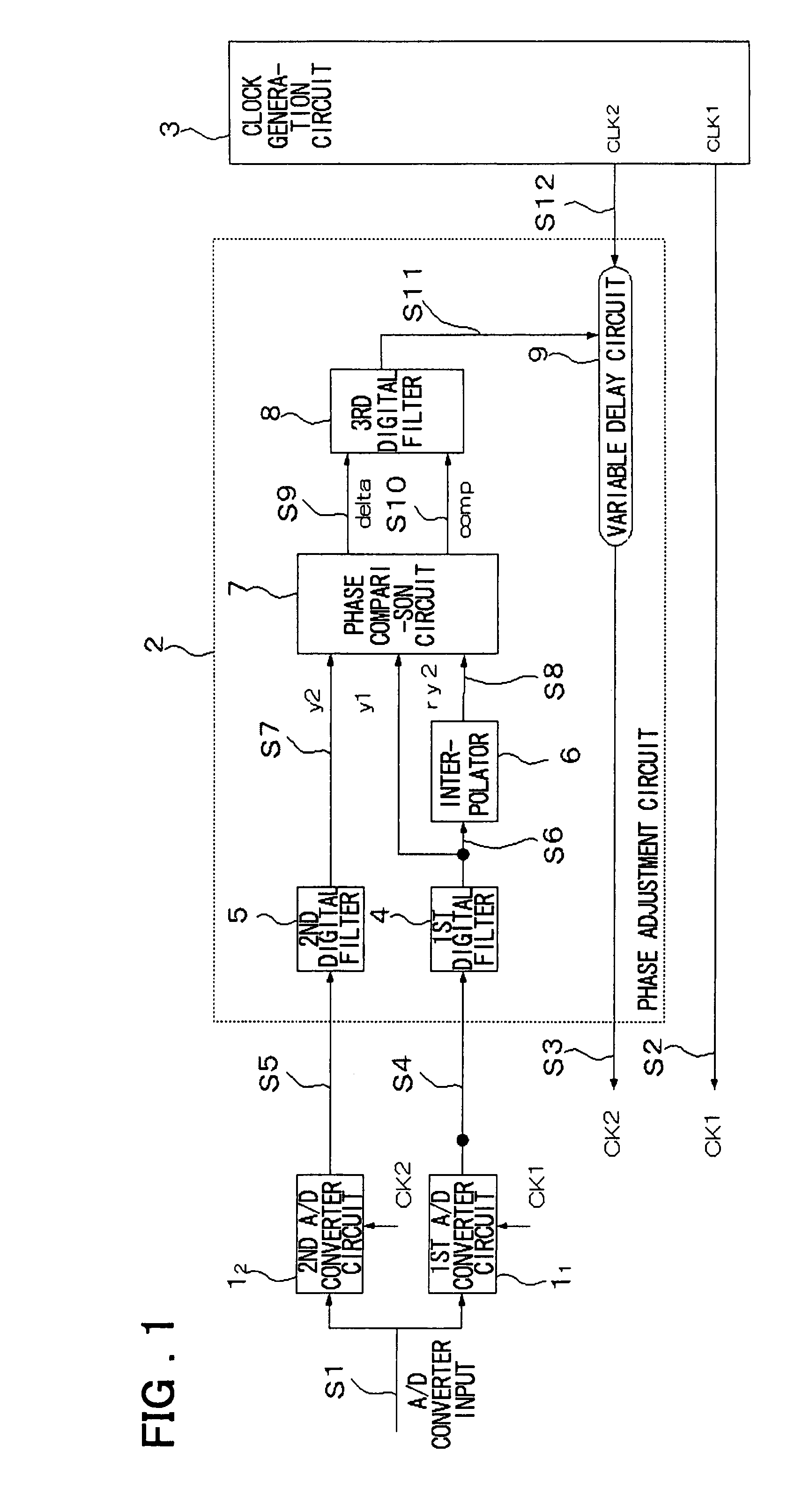
[0089]In the present invention, one of first and second A / D converter circuits forming a time-interleaved A / D converter device is used as reference, while the other of the first and second A / D converter circuits is used as the A / D converter circuit under adjustment (calibration). Using an output sequence (of a plurality of sampled values) of a digital filter that receives a converted output (a digital signal) of the A / D converter circuit on a reference side, an interpolator performs interpolation processing, thereby obtaining an interpolation value (approximate converted result) at a timing free of a clock skew on the side under adjustment. Then, the interpolation value is compared with an A / D converted result of the A / D converter circuit under adjustment, and the clock skew of a clock under adjustment is adjusted.

[0090]The present invention includes at least first and second A / D converter circuits (11, 12), and a phase adjustment circuit (2), corresponding to the fi...


PUM


Abstract

Disclosed is a time-interleaved A / D converter device that including first and second digital filters that respectively perform filter processing on output signals of first and second A / D converter circuits driven by first and second clocks, respectively, an interpolator that receives an output signal of the first digital filter and derives an interpolation value corresponding to a case where an input signal is sampled using the second clock signal free of a clock skew and having a predetermined phase relationship with respect to the first clock signal, a phase comparison circuit that receives the output of the first digital filter, an output of the second digital filter, and an interpolation signal from the interpolator, and outputs a first signal indicating a phase advance or a phase delay of the second signal responsive to a gradient of the input signal and a second signal indicating whether the output signal of the second digital filter matches the interpolation signal or not, a digital filter that receives the first and second signals output from the phase comparison circuit, and outputs zero when the second signal indicates a match and outputs a polarity of a value obtained b by selecting a positive value or a negative value according to the delay or advance indicated by the first signal and averaging selected values when the second signal indicates a mismatch, and a variable delay circuit that receives an output of the digital filter and changes a delay time of the second clock signal.

Description

RELATED APPLICATION[0001]This application is based upon and claims the benefit of priority from Japanese patent application No. 2006-179685, filed on Jun. 29, 2006, the disclosure of which is incorporated herein in its entirety by reference.FIELD OF THE INVENTION[0002]The present invention relates to a time-interleaved A / D converter device. More specifically, the invention relates to a time-interleaved A / D converter device that allows automatic adjustment of a skew of a clock signal.BACKGROUND OF THE INVENTION[0003]Recently, signal processing in applications of data communications or the like has been remarkably sped up. Accompanying this faster signal processing, faster conversion of an A / D (Analog to Digital) converter circuit is demanded. A highly accurate A / D conversion with a wide dynamic range is also demanded.[0004]As one of measures for the demands as described above, a time-interleaved A / D converter device, in which two or more A / D converter circuits are disposed in paralle...

Claims


Application Information

Patent Timeline
Patent Type & Authority Patents(United States)
IPC IPC(8): H03M1/10
CPCH03M1/0624H03M1/1215
Inventor UCHINO, SHINICHI
Owner NEC ELECTRONICS CORP
Learn More