Image processing apparatus and method

a technology of image processing and apparatus, applied in the field of image processing systems and methods, can solve the problems of inability to directly use color image data for one device in another device, ineffective for higher-order colors obtained by mixing a plurality of color materials, and inability to emphasize the importance of color management systems. to achieve the effect of facilitating color conversion

Active Publication Date: 2008-12-16
CANON KK
View PDF4 Cites 6 Cited by
  • Summary
  • Abstract
  • Description
  • Claims
  • Application Information

AI Technical Summary

Benefits of technology

[0012]The present invention provides an image processing system and method. Among other advantages, the image processing system and method facilitates color conversion for a device whose status varies momentarily, and allows the device to output desirable color at any time.

Problems solved by technology

The importance of color management systems cannot be over-emphasized.
Since different color reproduction devices have different color-reproduction ranges, color image data for one device cannot be directly used in another device.
Although this technique enables desirable color matching for primary colors, it less effective for higher-order colors obtained by mixing a plurality of color materials.
Nevertheless, even in MFPs, and in particular, when the output device is an electrographic printer, high quality reproduction of color cannot be obtained due to rapid daily changes in device status (for example, the color and quality of output images rapidly change due to changes in device status compared with images output by the ink-jet printer), so that output images vary even if the same profile is used in the same device.
This process is not only time-consuming, but it is also computation-intensive particularly for devices whose status often varies daily.

Method used


Image

  • Image processing apparatus and method
  • Image processing apparatus and method
  • Image processing apparatus and method

Examples


first embodiment

as Modified for when CMYK is not Directly Handled in Destination Profile

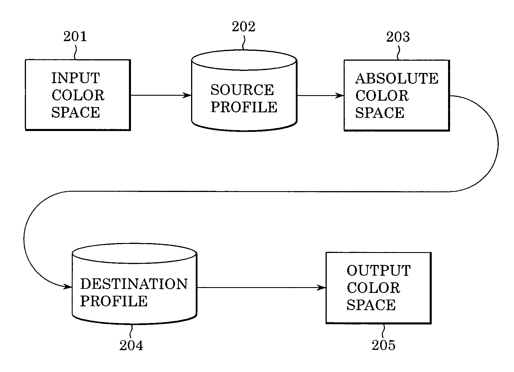
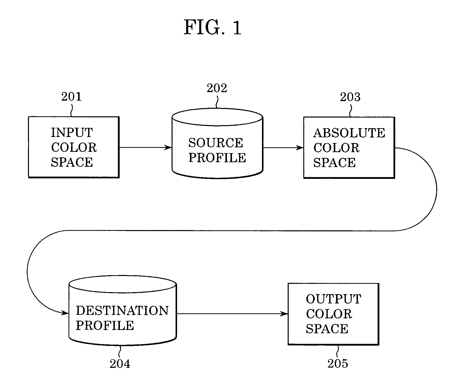
[0078]The first embodiment describes the case of using the destination profile having a look-up table for conversion from L*a*b* to CMYK. However, some printers do not have any destination profiles for direct conversion from L*a*b* to CMYK. FIG. 10 is a flowchart showing a data flow in a case in which a look-up table of a destination profile for conversion from an absolute color space to an output color space represents conversion from L*a*b* to RGB. In FIG. 10, a source profile 1002 is used to convert RGB image data 1001 to L*a*b* image data 1003. A destination profile 1004 is used to convert the L*a*b* image data 1003 to RGB′ image data 1005. The RGB′ image data 1005 is device-dependent RGB data. For an RGB printer, the RGB′ image data 1005 is output in unchanged form. For a CMYK printer, the RGB′ image data 1005 is converted to CMYK image data 1006 before being output.

[0079]Here, similarly to the case of CMYK...

second embodiment

as Modified for User Marking

[0125]Although the above-described second embodiment allows the user to determine the color reproduction accuracy and the processing speed by using the user interface shown in FIG. 18, the user may request correction of only a particular portion of an image. The following describes a modification of the second embodiment in order to cope with the above case.

[0126]When the user request is received in step S1702, and a particular object region of an image needs correction, the user is allowed to mark the region. One example is shown in FIG. 21. For example, it is assumed that the user wishes to correct a printed color of an arrow-shaped figure object 2101 at the top left. In this case, a circle mark 2102 is added to the figure object 2101. The mark may have any shape other than the circle.

[0127]An actual processing flow is shown in FIG. 22. A program corresponding to this flowchart is included in the color management program installed in the HDD 4 in the ma...


PUM

PropertyMeasurementUnit
coloraaaaaaaaaa
color conversion tableaaaaaaaaaa
color spaceaaaaaaaaaa

Abstract

An image processing system and method include allowing an output device to output patch-data items of plural multi-order colors represented by a first color space, measuring the color values, in an absolute color space, of the output patch-data items, calculating reference values by converting the plural multi-order colors represented by the first color space based on a first color conversion table containing correspondence between the first color space and the absolute color space, calculating distances between the color values measured by the color measuring means and the reference values, which correspond thereto, and correcting, based on the calculated distances, a second color conversion table containing correspondence between the absolute color space and an output color space.

Description

BACKGROUND OF THE INVENTION[0001]1. Field of the Invention[0002]The present invention relates generally to image processing systems and methods and more specifically to image processing systems and methods for performing color management.[0003]2. Description of the Related Art[0004]The importance of color management systems cannot be over-emphasized. With color management systems, color reproduction devices such as scanners, monitors and output devices can be characterized to provide image settings for optimal reproduction. Recently, with widespread colorization of output devices, the importance of a color-management technology for managing color information has become increased. Since different color reproduction devices have different color-reproduction ranges, color image data for one device cannot be directly used in another device. Accordingly, conventional systems are used wherein color image data corresponding to an input color space of an input device is temporarily converte...

Claims


Application Information

Patent Timeline
Patent Type & Authority Patents(United States)
IPC IPC(8): G06F15/00G03F3/08G06K9/00H04N1/46G06T1/00H04N1/60
CPCH04N1/603
Inventor MATSUZAKI, MASANORI
Owner CANON KK
Why Eureka
Try Eureka