Method and apparatus for integrated active-diode-ORing and soft power switching
a technology of soft power switching and active diode-oring, applied in the field of electric power systems, can solve the problems of adversely affecting reliability, electrical, mechanical, thermal and operational problems in electrical systems, and affecting reliability, and achieve the effects of improving reliability and safety
- Summary
- Abstract
- Description
- Claims
- Application Information
AI Technical Summary
Benefits of technology
Problems solved by technology
Method used
Image
Examples
second embodiment
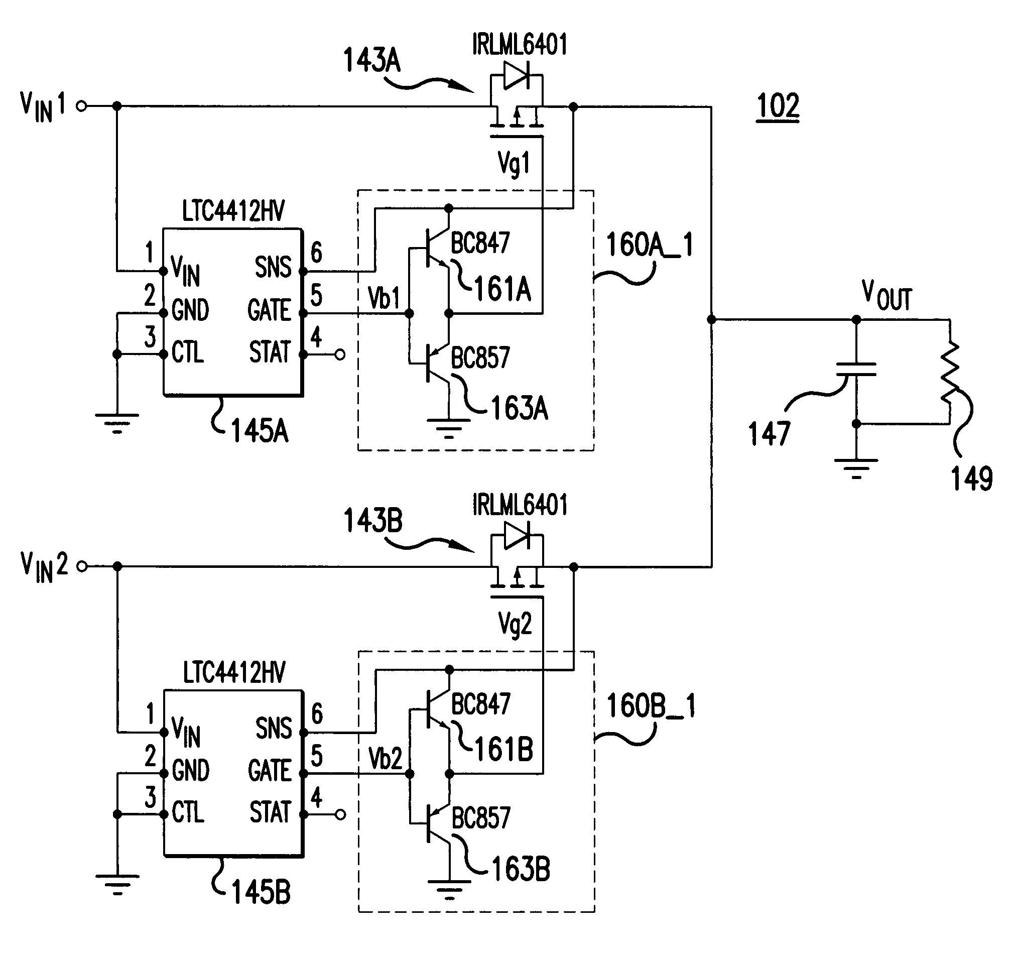
[0067]FIG. 5A is a block diagram of an electrical configuration containing an active ORing circuit with two FETs with driver according to the present invention. The electrical configuration in FIG. 5A is a complete active ORing circuit with two channels. The driver 160A_1 shown in the block in dashed lines connects to FETs 143A and 205A. The driver 160B_1 shown in the second block in dashed lines connects to FETs 143B and 205B.
[0068]The active ORing circuit in FIG. 5A has two input channels, but more input channels can be connected together. Each input channel has a controller (elements 145A and 145B), a switch (P-channel MOSFETs 143A and 205A, and P-channel MOSFETs 143B and 205B respectively), and a driver (160A_1 and 160B_1).
[0069]Drivers 160A_1 and 160B_1 are totem-pole drivers composed of a pair of NPN and PNP transistors (totem-pole with 161A and 163A for one channel, and totem-pole with 161B and 163B for the second channel).
[0070]The controller (elements 145A and 145B) may be ...
third embodiment
[0076]FIG. 6B is a block diagram of an electrical system incorporating soft start / stop into a multiple input / output power supply system using an active ORing circuit according to the present invention. FIG. 6B is an improvement on the typical / conventional circuit shown in FIG. 6A, obtained by incorporating soft start / stop into a multiple input / output power supply system using an active ORing circuit. The multiple power supply connecting system 311 shown in the dashed lines is the design improvement over the typical / conventional circuit shown in FIG. 6A.
[0077]In case of multi-channel input, along each channel a diode is connected in series with a resistor to isolate the inputs, as shown in FIG. 6B. The electrical system 105 in FIG. 6B includes an integrated active ORing circuit with soft-start / stop features for multi-channel inputs. The first channel uses an ORing system 90_1, a delay module 338_1, a diode D_1, and resistor R_1 in series with the diode D_1, with both R_1 and D_1 in p...
PUM
 Abstract
Description
Claims
Application Information
 - R&D
- Intellectual Property
- Life Sciences
- Materials
- Tech Scout
- Unparalleled Data Quality
- Higher Quality Content
- 60% Fewer Hallucinations
Browse by: Latest US Patents, China's latest patents, Technical Efficacy Thesaurus, Application Domain, Technology Topic, Popular Technical Reports.
© 2025 PatSnap. All rights reserved.Legal|Privacy policy|Modern Slavery Act Transparency Statement|Sitemap|About US| Contact US: help@patsnap.com


