
Method and system for adjusting the flight path of an unguided projectile, with compensation for jittering deviation

a technology of unguided projectiles and flight paths, applied in direction controllers, instruments, launching weapons, etc., can solve the problems of unsatisfactory delivery of unguided projectiles, inability to provide guidance control, and projectiles launched in ballistic trajectory by means of thrust producing devices such as bazookas

Active Publication Date: 2008-12-23
STATE OF ISRAEL MINIST OF AGRI & RURAL DEV AGRI RES ORG (A R O) (VOLCANI CENT)
View PDF18 Cites 5 Cited by
  • Summary
  • Abstract
  • Description
  • Claims
  • Application Information

AI Technical Summary

Benefits of technology

[0050]The projectile is preferably formed with elements that radially protrude from the projectile fuselage, said elements being insertable within complementary grooves formed within said launch tube, during loading of the projectile within the launcher, and being adapted for preventing rotation of the projectile within said launch tube, prior to the ejection time.

Problems solved by technology

In contrast, projectiles launched in a ballistic trajectory by means of a thrust producing device, such as a bazooka, without guidance control during the flight after launching are relatively inaccurate, and therefore generally have an effective range of up to 300 m.
It has been found that a major source of unguided projectile inaccuracy is the jittering of the associated launch tube that is produced at the time of launching.
The method proposed by the Davis Gun, as described in U.S. Pat. No. 1,108,717, although providing a reduction in the jittering, has not yet provided satisfactory results.

Method used


Image

  • Method and system for adjusting the flight path of an unguided projectile, with compensation for jittering deviation
  • Method and system for adjusting the flight path of an unguided projectile, with compensation for jittering deviation
  • Method and system for adjusting the flight path of an unguided projectile, with compensation for jittering deviation

Examples


Embodiment Construction

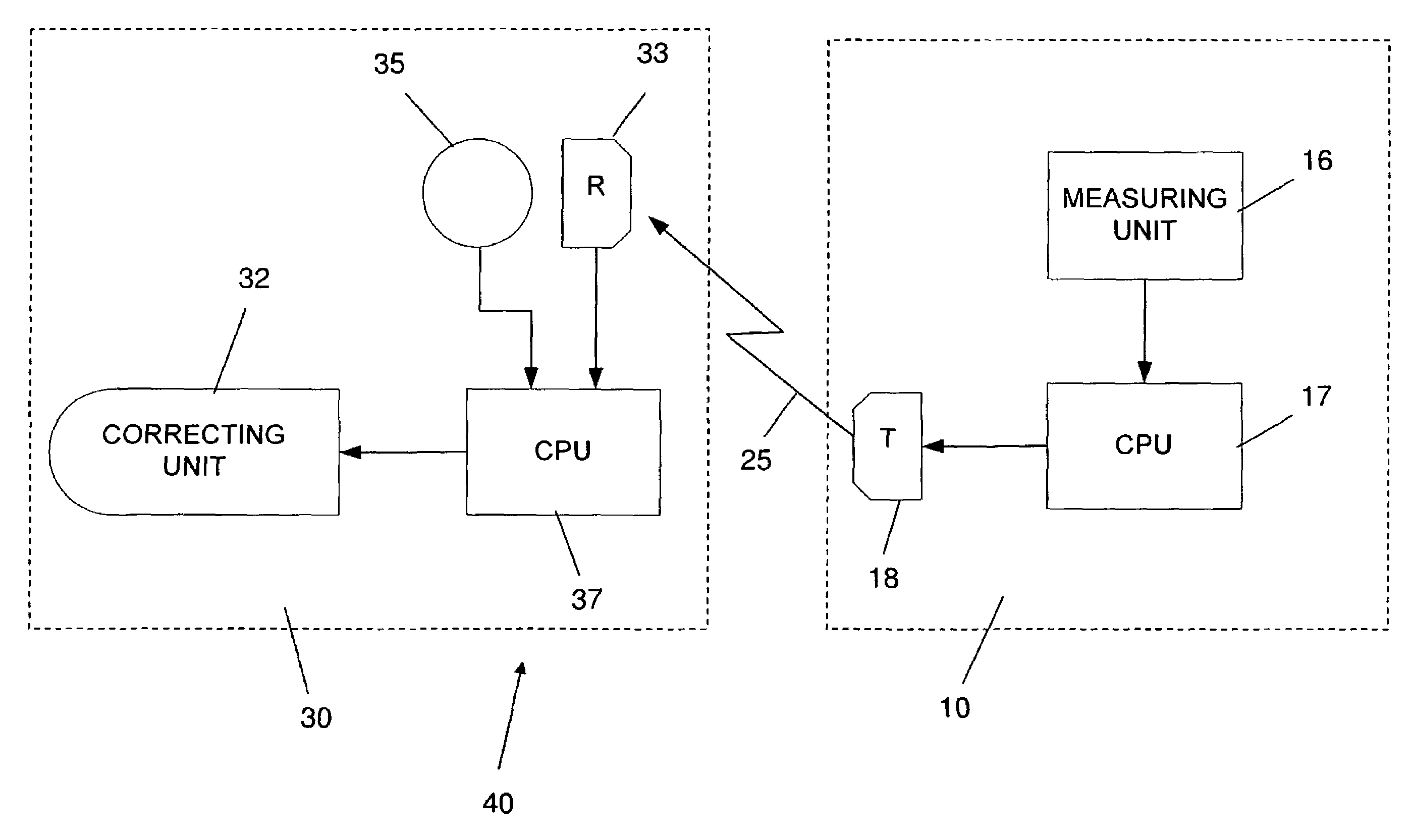
[0063]The present invention relates to a method and system for adjusting the flight path of an unguided projectile, immediately after launching, in order to compensate for inaccuracies that result from barrel recoil or jittering during the projectile firing. It will be understood that the term “jittering” throughout the specification also refers to recoil.

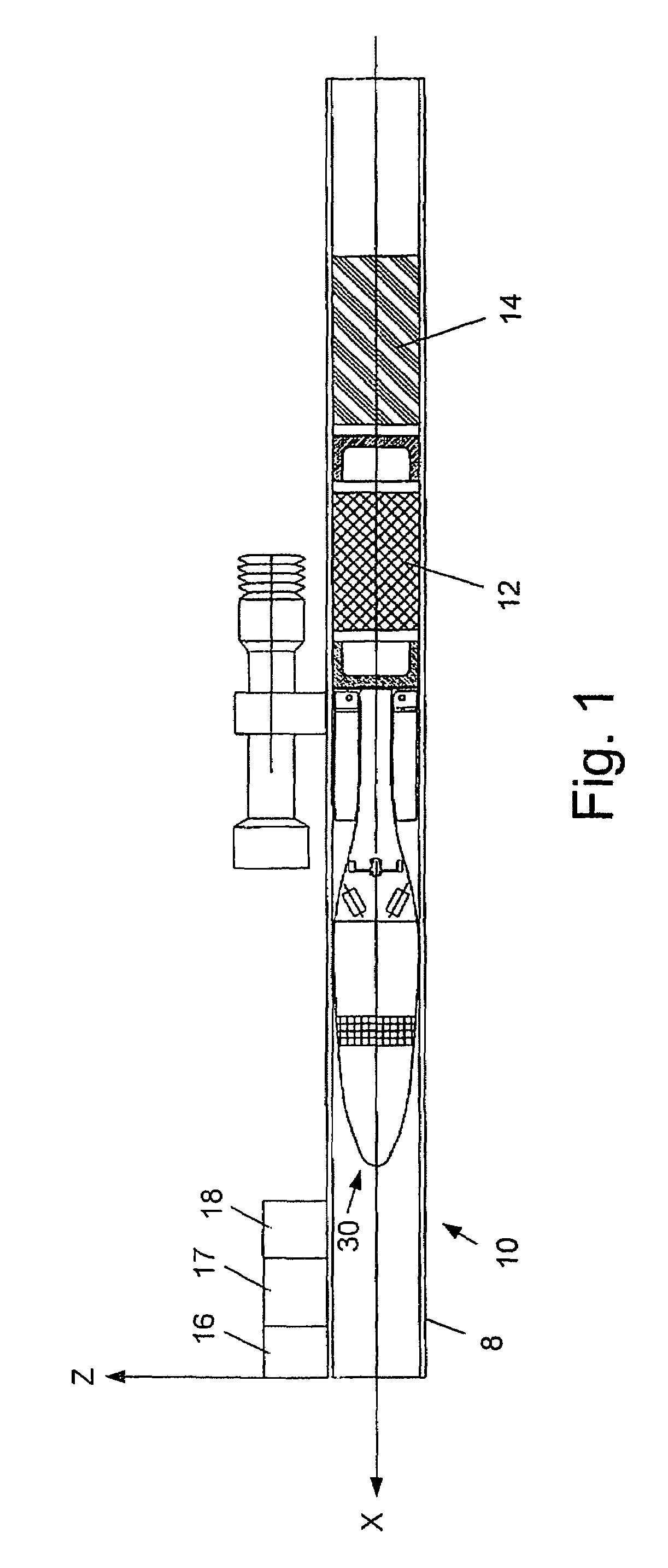
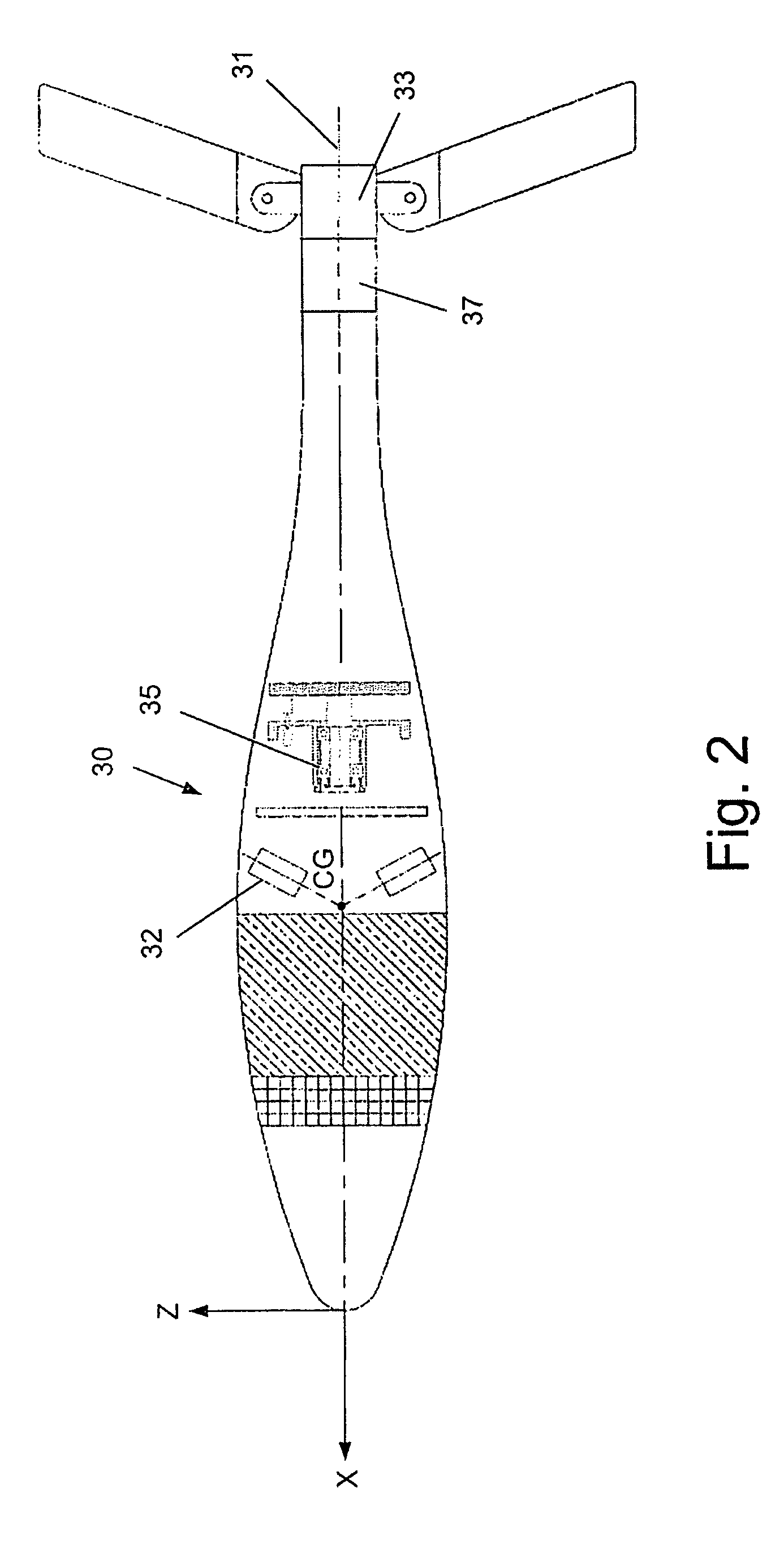
[0064]FIG. 1 schematically illustrates an exemplary projectile launcher, generally designated by numeral 10, in which a projectile, generally designated by numeral 30, is loaded. Launcher 10 may be fixed onto the barrel of a rifle, may be an independent unit, may be portable such as being a shoulder-carried launcher, or may be deployed in several types of naval or aircraft weaponry.

[0065]The illustrated projectile launcher 10, according to one embodiment of the invention, is configured as a Davis gun for obtaining a reduced jittering, with a solid propellant 12 and compensating mass 14 being loaded in launch tube 8, rearward to pro...


PUM


Abstract

A method for adjusting the flight path of an unguided projectile, which comprises the steps of: (a) Measuring the magnitude and direction of the jittering of a projectile launch tube, at an ejection time of a projectile from the launch tube; (b) Measuring a velocity deviation of the projectile from a nominal velocity; (c) Measuring an angular deviation of the sight of the launch tube, being equal to the angular deviation between a line coinciding with the direction of gravity and a line passing through the center of the launch tube and the center of the sight; (d) Determining a compensating impulse vector to be applied to the projectile during an initial flight path thereof based on the magnitude and direction of the jittering, velocity deviation and angular deviation; and (e) Applying the compensating impulse vector to the projectile by activating a flight correction unit, the thrust developed by the flight correction unit suitable for adjusting the flight path of the projectile by a magnitude and direction substantially equal to that of the compensating impulse vector.

Description

FIELD OF THE INVENTION[0001]The present invention relates to a method and system for adjusting the flight path of an unguided projectile, immediately after launching, in order to compensate for inaccuracies that result from barrel jittering during the projectile firing.BACKGROUND OF THE INVENTION[0002]Three types of short range missiles, i.e. with a range generally of less than 1 km, are known:[0003]Missiles with homing guidance that can be locked on a desired target (very accurate);[0004]Beam-riding missiles (less accurate than those with homing guidance); and[0005]Inertially guided missiles (less accurate than beam-riding missiles).[0006]In contrast, projectiles launched in a ballistic trajectory by means of a thrust producing device, such as a bazooka, without guidance control during the flight after launching are relatively inaccurate, and therefore generally have an effective range of up to 300 m.[0007]Several methods have been employed in the prior art in order to improve the ...

Claims


Application Information

Patent Timeline
Patent Type & Authority Patents(United States)
IPC IPC(8): F41G7/00F41F3/04F42B15/01F42B12/00F42B30/00F42B15/00F41G3/10F41G3/12F41G7/30
CPCF41G3/10F41G3/12F41G7/306
Inventor YEHEZKELI, ODEDKUNREICH, IRAD
Owner STATE OF ISRAEL MINIST OF AGRI & RURAL DEV AGRI RES ORG (A R O) (VOLCANI CENT)
Learn More