Non-invasive electronic method and apparatus for measuring blood pressure

a blood pressure and pulse rate technology, applied in the field of non-invasive electronic methods and instruments for measuring blood pressure, can solve the problems of limiting the application difficult to overcome, and time-consuming, and achieve the effect of improving the safety of blood pressure measurement, improving accuracy, and improving the degree of agreement with the real situation in the clini

Active Publication Date: 2008-12-23
SHENZHEN MINDRAY BIO MEDICAL ELECTRONICS CO LTD
View PDF6 Cites 27 Cited by
  • Summary
  • Abstract
  • Description
  • Claims
  • Application Information

AI Technical Summary

Benefits of technology

[0042]According to the above-mentioned apparatus of the present invention, the apparatus further comprises a precise amplifier having an input terminal connected with an output of the first pressure sensor, wherein the precise amplifier outputs both a pulse signal amplified by a two-stage amplification circuit and a pressure signal to an A / D converter circuit. Moreover, the apparatus may further comprise a gain control and reference voltage circuit which has an output terminal connected with the two-stage amplification circuit. The two-stage amplification circuit comprises a preamplifier and a postamplifier which are connected in series, wherein an output of the preamplifier or the postamplifier is connected with a first resistor, while a second resistor is in parallel connected with or not connected with the first resistor via the gain control and reference voltage circuit, which is determined by pins A, B and C of the gain control and reference voltage circuit controlled by SETP and AN_MODE signals from the first microprocessor. Compared with the circuit design of prior art, the first advantage of the present invention is that the connection structure of the gas path is optimized, and the automatic and accurate “zero pressure point” calibration of the cuff pressure is performed without the influence of the residual pressure in the gas path, which improves the accuracy of the measurement of cuff pressure.
[0043]The second advantage is that, the independent timing can be performed by means of a set of independent timing circuit, which can really implement the independent timing in the module level and improve the safety during measuring of blood pressure.
[0044]The third advantage is that, with the method according to the present invention, the envelope curve of the PW amplitude trend can be recovered accurately, and the obtained average pressure shows higher degree of agreement with the real situation in clinic.

Problems solved by technology

Continuously uniform deflation leads to time increase for blood pressure measurement, and it is hard to overcome an influence on the arm movement and the body position change, which would limit its application.
However, there exists circuit drift and it can not be ensured that the static pressure in the cuff during multiple blood pressure measurement process always drops to nearly “zero”, which will lead to the following results: i) the possible failure in zero correction, and ii) the pressure value deviation due to the offset of zero point even in case of really zeroing.
In short, an adverse effect would be exerted on the accuracy in detecting the cuff pressure.
However, this blood pressure module does not perform a complete safety independent timing and requires the cooperation of the upper computer, which may cause potential danger for the application of such blood pressure measurement module.
Therefore, there are the disadvantages of fitting with linear trend in that the envelope curve of the PW amplitude can not be correctly recovered, and the average pressure, the systolic pressure and the diastolic pressure can be not calculated accurately.

Method used


Image

  • Non-invasive electronic method and apparatus for measuring blood pressure
  • Non-invasive electronic method and apparatus for measuring blood pressure
  • Non-invasive electronic method and apparatus for measuring blood pressure

Examples


Embodiment Construction

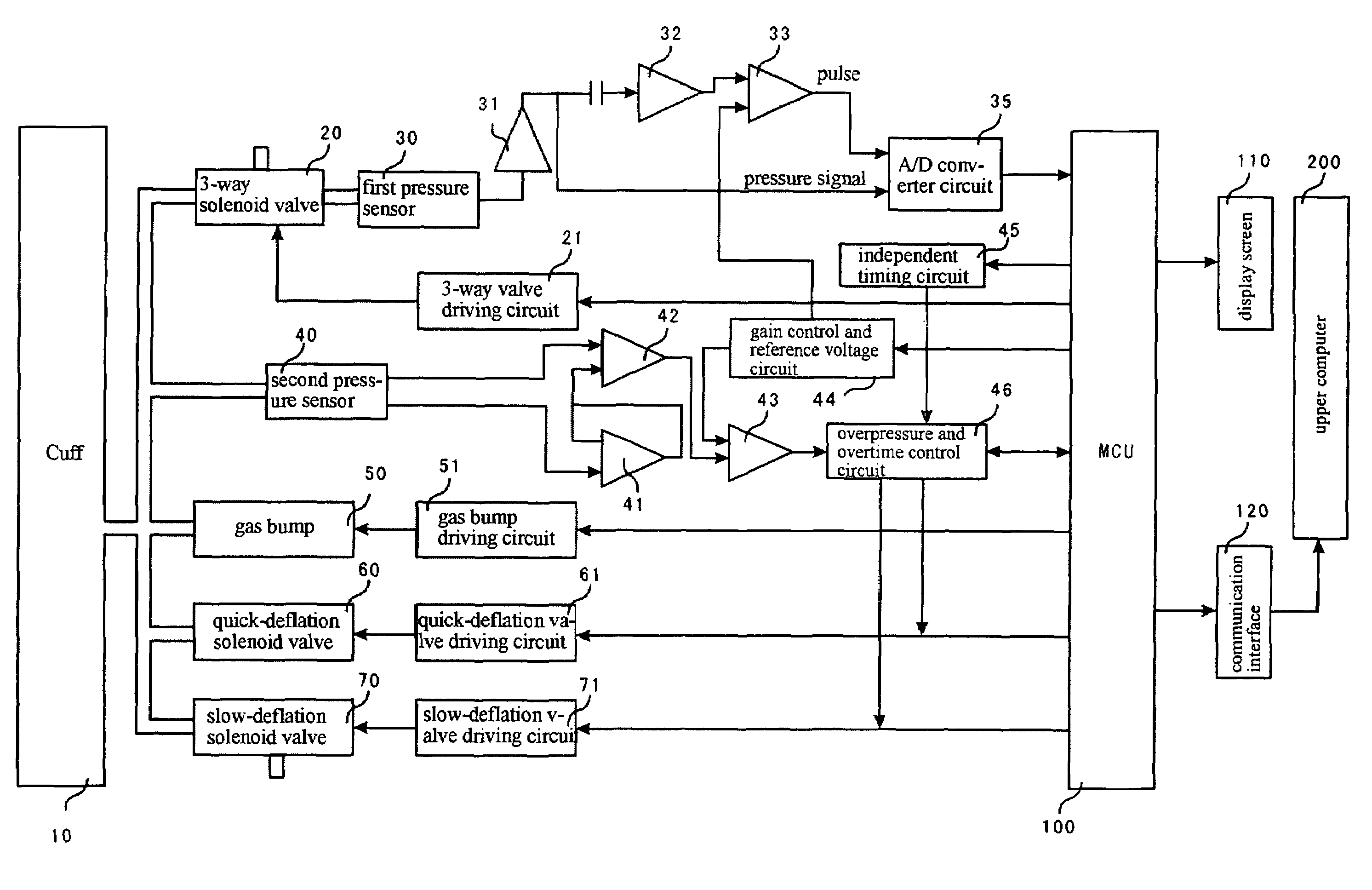
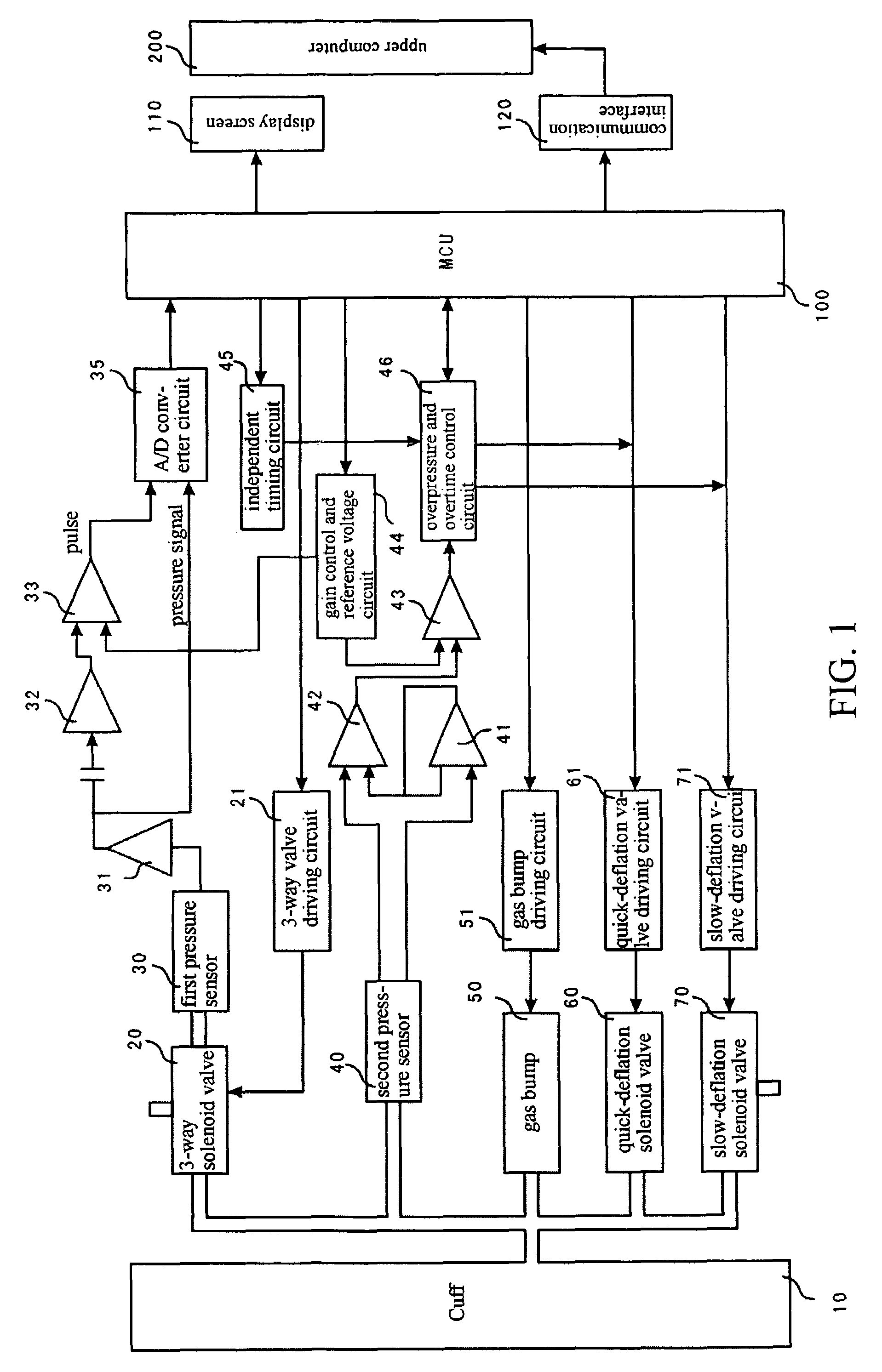
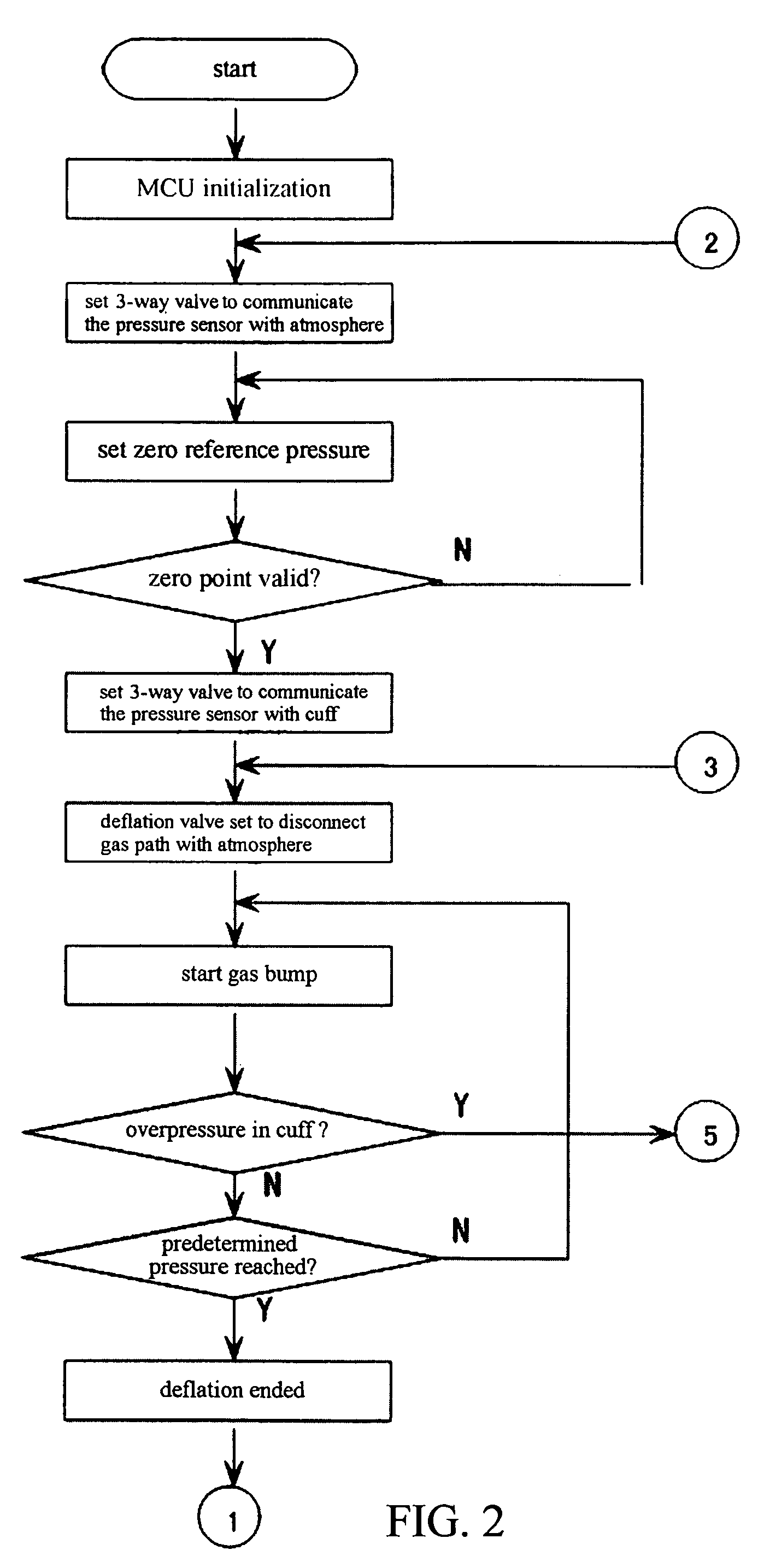
[0052]A non-invasive electronic method for measuring blood pressure according to the present invention includes the following steps:

[0053]i. inflating a cuff communicated with a first pressure sensor which has been zeroed, and then stopping inflation after a cuff pressure reaches a preset value;

[0054]ii. deflating the cuff at a preset speed and detecting whether a pulse signal occurs;

[0055]iii. after the pulse signal is detected, processing data with an algorithm for recovering a trend envelope of an oscillating pulse wave, and displaying the measured blood pressure;

[0056]during the step i, the first pressure sensor is zeroed in a state of communicating with atmosphere; and

[0057]during the step iii, the algorithm for recovering the trend envelope of the oscillating pulse wave is a nonlinear fitting algorithm.

[0058]In the non-invasive electronic method for measuring blood pressure according to the present invention, zeroing operation may be performed periodically or prior to every me...


PUM


Abstract

Provided is a non-invasive electronic method and apparatus for measuring blood pressure, in which the data is processed with an algorithm of non-linear fitting for recovering trend envelope of an oscillating PW by a firmware, so that the trend envelope of PW amplitude can be recovered accurately, and the obtained average pressure shows higher degree of agreement with the real situation in clinic. In this apparatus, a 3-way solenoid valve (20) is arranged between a cuff (10) and a first pressure sensor (30), wherein the common port of the 3-way solenoid valve (20) is connected with the first pressure sensor (30), the normally open port thereof connected with the cuff (10), and the normally closed port thereof connected with the air atmosphere during zeroing process. Moreover, an independent timing circuit (45) is provided additionally. In the measurement method of the present invention, the zeroing is performed with the help of the 3-way solenoid valve (20). Once a state of overtime or overpressure occurs, an air bump (50) is immediately closed, and a quick-deflation solenoid valve (60) is opened so that the pressure in the cuff (10) is released to ensure safe application.

Description

FIELD OF THE INVENTION[0001]The present invention relates to a method and an apparatus for measuring blood-pressure and pulse rate for diagnosis, and particularly to a non-invasive electronic method and apparatus for measuring blood pressure which can correctly calibrate zero pressure, and process the data acquired during electronic blood pressure measurement by an algorithm of fitting for recovering a trend envelope of oscillating PW (i.e. pulse wave).BACKGROUND OF THE ART[0002]The non-invasive methods for measuring blood pressure in prior art employ the oscillometric method on the basis of cuff PW. The non-invasive method for measuring the blood pressure of human body mainly comprises an auscultatory method using Korotkoff sound (simply referred as Korotkoff sound method) and proportional coefficient method using cuff oscillating wave (simply referred as oscillometric method).[0003]Korotkoff Sound method means that, the experienced medical personnel use a stethoscope, a mercury pr...

Claims


Application Information

Patent Timeline
Patent Type & Authority Patents(United States)
IPC IPC(8): A61B5/02
CPCA61B5/02225A61B5/0225
Inventor YE, JILUNTAO, BOYU, SHENYAN
Owner SHENZHEN MINDRAY BIO MEDICAL ELECTRONICS CO LTD
Why Eureka
Try Eureka